Graphics Reference
In-Depth Information
is needed to get a good understanding of what happens to vertex coordinates
as they go through the various stages of the OpenGL ES 3.0 pipeline.
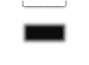
Output of
vertex shader
Clipping
Perspective
Division
Division
Viewport
Transformation
To rasterization
stage
Figure 7-6
OpenGL ES Primitive Assembly Stage
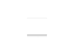
Figure 7-7 shows the coordinate systems as a vertex goes through the vertex
shader and primitive assembly stages. Vertices are input to OpenGL ES in
the object or local coordinate space. This is the coordinate space in which
an object is most likely modeled and stored. After a vertex shader executes,
the vertex position is considered to be in the clip coordinate space. The
transformation of the vertex position from the local coordinate system (i.e.,
object coordinates) to clip coordinates is done by loading the appropriate
matrices that perform this conversion in appropriate uniforms defined in
P
Perspective
Division
e
Vertex
Shader
Viewport
Transformation
Object
Coordinates
Normalized
Device
Coordinates
Clip
Coordinates
Window
Coordinates
Figure 7-7
Coordinate Systems