Information Technology Reference
In-Depth Information
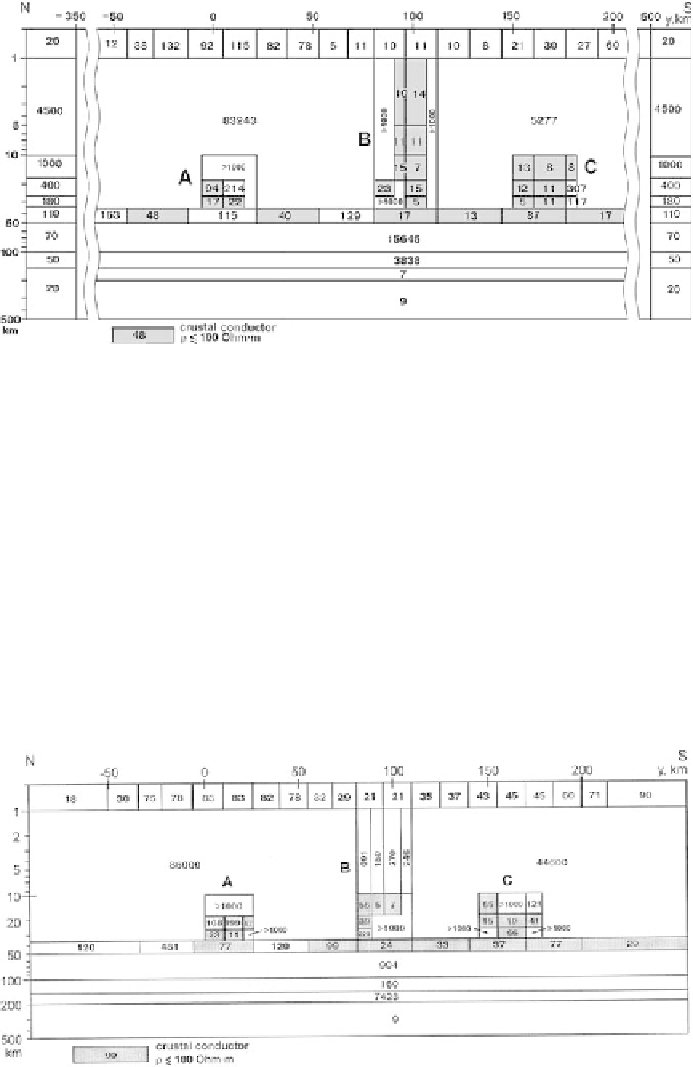
Fig. 12.27
Model TS-5; partial inversions have been performed using the blocky II2DC program
with a symmetric normal background; resistivity values in Ohm
m are shown within blocks; blocks
of lower crustal resistivities are shaded (cf. Figs.12.27 and 12.24)
·
,
⊥
) used in constructing the TS-4 model. Figure 12.28 displays the
TS-6 model obtained by parallel inversion. In this model: (1) resistivity contrasts in
the sedimentary cover are significantly smoothed, (2) the resistivity contrast in the
upper, highly resistive crust is also significantly smoothed, (3) the conductive zones
A and C are resolved with some degree of certainty, while the central through-
the-crust conductive zone B is completely destroyed, (4) the contrast between the
two edge resistivities in the crustal conducting layer is much lower, and (5) the
monotonic decrease of the mantle resistivity is disturbed (a highly resistive layer
appears in the conductive mantle). We see that the parallel inversion of all response
functions in use impairs the information on the Earth's interior.
⊥
and
⊥
has been per-
formed using the blocky II2DC program with an asymmetric normal background; resistivity values
in Ohm
,
⊥
,and
Fig. 12.28
Model TS-6; the parallel inversion of Re
W
zy
,Im
W
zy
,
m are shown within blocks; blocks of lower crustal resistivities are shaded (cf. Figs.12.16
and 12.24)
·