Information Technology Reference
In-Depth Information
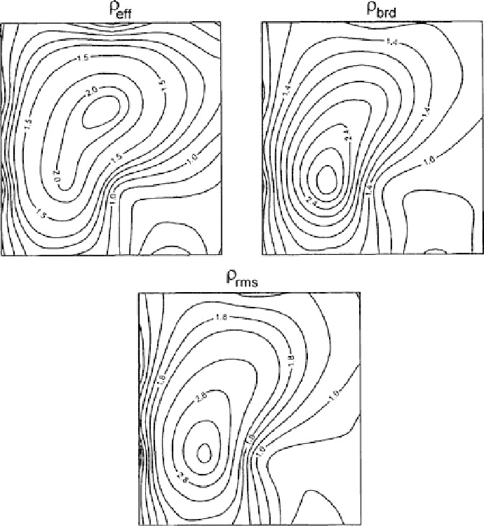
Fig. 11.45
Maps of apparent resistivities
eff
,
brd
,
rms
in the model shown in Fig. 2.3. The model
contains a near-surface resistive
-shaped inclusion
plotted at
T
-shaped max-
imum reflecting the inclusion shape. Note that over the entire range of low fre-
quencies relating to the
S
1
- and
h
-intervals the form of the contour lines is hardly
changed. Note also that the most adequate inclusion shape is given by
=
640 s. All three maps exhibit more or less smoothed
eff
, whereas
rms
gives the largest amplitude of the
-shaped maximum.
Next we will consider the pseudo-sections and pseudo-topograpfies of the mag-
netotelluric and magnetovariational response functions that can give the most picto-
rial image of geoelectric structures.
Figure 11.46 provides a synthetic example of pseudo-sections of apparent resis-
tivity and impedance phase. A two-dimensional model consists of a conductive
layer,
1
=
·
2
=
·
10 Ohm
m, and a resistive layer,
10000 Ohm
m, resting on