Hardware Reference
In-Depth Information
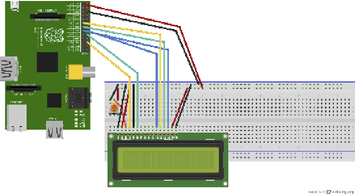
FIGURE 9-2
Circuit diagram for wiring the LCD screen and potentiometer
•
Pin 6 (EN) connects to the Raspberry Pi GPIO 24 (green male-to-female
cable).
•
Skip LCD Pins 7, 8, 9 and 10.
•
Pin 11 (D4) connects to the Raspberry Pi GPIO 23 (blue male-to-female
cable).
•
Pin 12 (D5) connects to the Raspberry Pi GPIO 17 (yellow male-to-female
cable).
•
Pin 13 (D6) connects to the Raspberry Pi GPIO 27 (green male-to-female
cable).
•
Pin 14 (D7) connects to the Raspberry Pi GPIO 22 (blue male-to-female
cable).
•
Pin 15 (LED +) goes to the Raspberry Pi 3.3V (red male-to-female cable).
•
Pin 16 (LED -) goes to the Raspberry Pi ground or GND (black male-to-
female cable).
•
On the potentiometer, connect the left pin to the ground or negative blue
strip of the breadboard (black male-to-male cable), and the right pin to the
3.3v or positive red strip of the breadboard (red male-to-male cable).
5.
Double-check the diagram (Figure 9-2) and picture (Figure 9-3) to check that you
have wired up your LCD and potentiometer correctly. When you are happy that
your wiring is correct, plug your Raspberry Pi, complete with SD card, into a
monitor, keyboard, mouse, network (Ethernet) cable, and inally, power supply.