Information Technology Reference
In-Depth Information
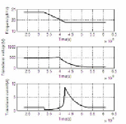
(a) Being loaded (b) Being unloaded
ω
using the proposed method
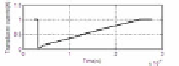
Fig. 5.
Voltage and current being varied with
s
When the transducer being loaded shown in Fig.5(a), the current decreases to zero
instantly. The voltage and current both increase steadily, which is the same as using
the traditional method. When transducer being unload shown in Fig.5(b), the current
also decreases to zero instantly, and subsequently increases to 9A right after fre-
quency tracking completes. Though the current overshoot appears, the proposed
method takes advantages over the traditional method of its overshoot value and over-
shoot time.
5.3 Parameters Effect on Characteristic of the Novel Method
The set of
>>
A
is the base of the proposed method. The effect of three pa-
rameters on the overshoot are analyzed below. Supposing that
τ
τ
>>
τ
C
B
−
5
, over-
shoot of the voltage and currentare are simulated and shown in Figure 6 and Figure 7
under both conditions of the transducer being loaded and unloaded.
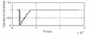
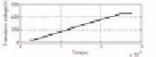
As shown in Figure 6, voltage and current both won't be overshooted when trans-
ducer being load. It is noted that the regulation process will be shorter when speed of
τ
=
5
×
10
s
C
τ
=
5
×
10
−
4
s
τ
=
5
×
10
−
6
s
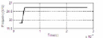
(a) Frequency tracking (b)
,
A
B
−
4
−
6
−
3
−
6
τ
=
5
×
10
s
τ
=
1
×
10
s
τ
=
2
.
5
×
10
s
τ
=
5
×
10
s
(c)
,
(d)
,
A
B
A
B
Fig. 6.
Overshoot of the voltage and current when the transducer being load


Search WWH ::

Custom Search