Information Technology Reference
In-Depth Information
VWDUW
GHWHFWLQJ
8
SY
ˈ
,
SY
<
3
W
3
W
"
1
<
1
ZRUNLQFXUUHQWVRXUFH
PRGHOG3G8 !
1
1
DURXQG033 "
G3
W
GX
W
G3
W
GX
W
DURXQG033
˛
G3
W
GL
W
G3
W
GL
W
<
<
,
V
G3GX
3,FRQWURO
8
R
G3GL
3,FRQWURO
Ň,
W
,
W
Ňİ
Ň8
W
8
W
Ňİ
<
3N3N
1
Q VLJQG3 GX
<
1
Q!
1
1
PQ!"
PQ!"
<
<
X X¨X
P Q
X X¨X
P Q
X X¨X
P Q
X X¨X
P Q
UHWXUQ
Fig. 3.
Improved Algorithm flow chart
4 Simulation Experiment
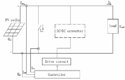
A block diagram of the main circuit system is shown in Fig. 4. Controlling algorithm
of the entire system is achieved by the MCU. The system is consisted by photovoltaic
modules, DC-DC converter and load.
Photovoltaic modules will adopt solar panels,its parameters: open-circuit voltage
U
oc
= 21.0 V; short-circuit current I
s
= 0.33A; maximum power corresponding to the
output voltage U
mpp
= 17.0 V; maximum power corresponding to the output current
I
mpp
= 0.29A; the maximum output power P
m
= 5.0W.Then according to the PV output
voltage, temperature, illumination intensity, short-circuit current and open circuit
voltage temperature coefficient calculate the output current. The traditional P&O
Fig. 4.
The main circuit diagram of the system


Search WWH ::

Custom Search