Graphics Reference
In-Depth Information
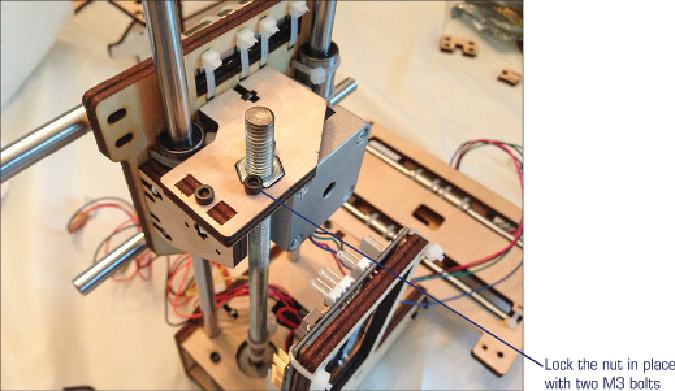
Figure 3.17
The lead screw will control the up/down movement of the hot-end.
Next you'll insert two additional 6.5” metal rods through the Y-axis bearings. The
same as with the X axis, you take the Y-axis Mini-Assembly 2 (shown back in
Figure 3.13
)
and attach it to the Y-axis Mini-Assembly 1 with zip ties around the
metal rods. Make certain these zip ties are as tight as you can get them - the tighter
the better. And while you're at it, go ahead and tie a small knot and secure it with
an M3 bolt and nut to the inside of the long Y-axis piece, as shown in
Figure 3.18
.
(In
Figure 3.18
, you can also see the zip ties holding the longer Y-axis assembly.)
Search WWH ::

Custom Search