Graphics Reference
In-Depth Information
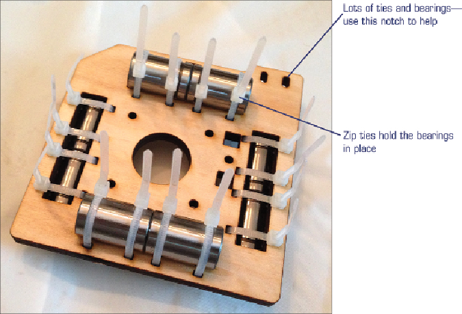
Again, pay attention to the location of the zip tie nubs as well as the orientation
of the wooden pieces. Use the photos as visual clues. For example, in
Figure 3.12
,
you'll see that an angled notch is cut into this normally square piece. That angled
notch will help you orient the piece and show you where the zip tie nubs are to be
located so they don't interfere with any moving parts.
Figure 3.12
The Y-axis assembly begins with this piece.
Finish attaching a few more pieces to the wooden piece with all the bearings, and
then bolt in the Y-axis motor (again, using photos to help you determine which
side of the wooden piece the motor should be attached to as well as the direction
of the wires). I'm going to call this Y-axis Mini-Assembly 1. Set this piece (with
the motor) aside for a moment.
You'll now build the Y-axis Mini-Assembly 2, which is fairly straightforward.
When you're done, you'll have a long Y-axis assembly that looks like the one in
Search WWH ::

Custom Search