Graphics Reference
In-Depth Information
Midway Through Assembly Observations
When it comes to the two 10” metal rods, you need to be very careful when insert-
ing them through the cut holes. The instructions recommend using a hammer or a
rubber mallet, and I highly recommend the rubber mallet option. The keys to this
step are to hold each rod perfectly vertical as you hammer it into the circular hole.
You're going to feel resistance because the holes are slightly smaller in diameter
because the rods must be held securely and tightly for the Z-axis to work properly.
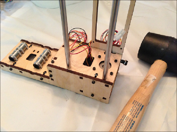
You can see in
Figure 3.10
that I was successful in getting both metal rods inser-
ted; pay attention to the instructions that tell you to place some extra wood pieces
underneath the bottom of the base so it doesn't crack.
Figure 3.10
The Z-axis metal rods are inserted.
Next, use zip ties to connect the bottom X-axis plate shown in
Figure 3.11
to the
two 6.5” metal rods inserted into the X-axis bearings. These rods should move left
and right easily, with almost no resistance. Pay attention to how the nubs of the
zip ties rest on top of this plate and not the bottom. You also want to make certain
the small hole on the plate is on the left (when looking from the front). This hole
Search WWH ::

Custom Search