Geoscience Reference
In-Depth Information
(a)
Gauge
Deflection of air by rain gauge (horizontal flow)
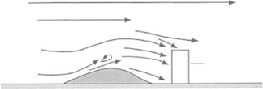
(b)
Gauge
Upward deflection over gauge (turbulent flow)
Figure 12.1
Air flow around
a standard rain gauge
standing on the ground: (a)
with no nearby obstruction
and (b) and (c) with nearby
obstruction at different
distances up wind. (From
Sumner, 1988, published with
permission.)
(c)
Gauge
of raindrops, but persistent flow features in the local turbulent field (Fig. 12.1)
alter the wind flow across the top of the gauge and the average path of the rain-
drops and snowflakes entering, or failing to enter, the funnel.
Larger surrounding features such as trees, walls, and buildings upwind of the
gauge can induce persistent flow distortions in the overall wind field to which the
gauge is exposed, or they may shade the gauge from rain. Consequently, selecting
a gauge site is a compromise between potential over-exposure to high wind speed
which worsens the local catch errors, and the possibility that large upwind obstruc-
tions shade the gauge and reduce the catch. To reduce the effect of large-scale
upwind obstructions it is often recommended that the angle such obstacles sub-
tend with the ground when viewed from the gauge site is less than 30°.
Minimizing the percentage loss of catch due to local flow distortion is a less
tractable problem, but efforts have been made to do this at exposed sites. In gen-
eral, the approach is to establish wind flow across the gauge that is as near as pos-
sible horizontal while seeking to reduce the wind speed. Figure 12.2 illustrates
some of the methods that have been recommended for this purpose. Figure 12.2a
illustrates the method recommended by the UK Meteorological Office in which a
turf wall is built 1.5 m from and surrounding the gauge with height equal to that of
the gauge. The assumption is that the wind flow is moved upward and has time to
become horizontal before passing across the top of the gauge. An alternative and