Biomedical Engineering Reference
In-Depth Information
9 mm
6
Air
Filter
9
Image Analyzer
SP
8
2
5
4
7
11
Influent
Sampling
Port
PP
Air
Porous Media Reactor
Nutrient
Media
E
uent Sampling Port
10
3
1
Sampling
port
Steel mesh
Perspex wall
Pressure
transducer
Steel
mesh
Nitrogen
(oxygen free)
P5
Aquifer material
Sampling ports
(rubber
septum
equiped)
P4
Air
filters
P3
Aquifer
material
Stainless steel
thread (swagelock)
Glass
tubes
Air
filter
P2
Steel mesh
Pressure
sensor
Glass
bottle
Ta p
Peristaltic
pump
Glass
bottle
Sampling
port
Computer
Treated Bolivar
waste water
Data logger
Battery
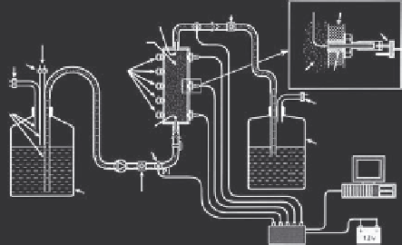
FIGURE 5.3
Schematics of experimental setups to study biofilm formation in porous media.
Top left: Capillary flowcells used by Cunningham et al. (1991); Top right:
artificial fracture setup used by Castegnier et al. (2006); Bottom: column
setup utilized by Rinck-Pfeiffer et al. (2000). The two flowcells systems (top)
both allow for direct optical interrogation of the system. The column setup
(bottom) allows for more realistic porous media conditions but does not
permit direct optical interrogation. The fracture and column flow systems
allow for limited spatially resolved assessments of hydraulic conductivity due
to multiple piezometers or pressure transducers. See cited sources for more
detailed explanations of the experimental setups. (Top Left: Reprinted with
permission from Cunningham, A. B., Characklis, W. G., Abedeen, F., and
Crawford, D.,
Env. Sci. Tech.,
25, 1991. c
1991, American Chemical Soci-
ety. Top Right: Reprinted from, Castegnier, F., Ross, N., Chapuis, R.P.,
Deschenes, L., and Samson, R.,
Water Res.,
40, 2006. c
2006—with permis-
sion from Elsevier. Bottom: Reprinted from, Rinck-Pfeiffer, S., Ragusa, S.,
Sztajnbok, P., and Vandevelde, T.,
Water Res.
, 34, 2000. c
2006—with per-
mission from Elsevier.)

Search WWH ::

Custom Search