Biomedical Engineering Reference
In-Depth Information
+
+
+
+
+
+
+
+
+
+
+
+
+
+
+
+
+
+
+
+
+
+
+
+
+
+
+
+
+
+
+
+
+
+
+
+
+
+
+
+
+
+
+
+
+
+
+
+
+
+
+
+
+
+
+
+
+
+
+
+
+
+
+
+
+
+
+
+
+
+
+
+
+
+
+
+
+
+
+
+
+
+
+
+
+
+
+
+
+
+
+
+
+
+
+
+
+
+
+
+
-1.0
0.6
2.2
3.8
5.4
7.0
8.6
10.2
11.8
13.4
15.0
µ
m
19.98
0.5N
0 mm
Penetration depth
2.04
4.04
6.03
8.03
10.02
12.02
14.01
16.01
18.00
0.40
0.80
1.20
1.60
2.00
2.40
2.80
3.20
3.60
4.00
Residual depth
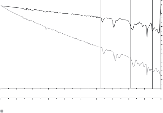
Figure 21.6.
Coating adhesion studies using micro scratch test system: The Figure represents
the penetration depth and residual depth as a function of applied load. The coating behaves
like any ceramic coating on metallic substrates, exhibiting resilience until the fi rst crack (at
load LC
1
= 12.5 N) is initiated, leading to complete rupture of the coating (at LC
2
= 16.2 N) and
subsequent total delamination as the load is increased (at LC
3
= 19 N).
TABLE 21.7. Critical Loads for T i N and DLC Coatings on CP Titanium and T i 6 A l 4 V Substrates
Critical loads (N)
TiN coating on Ti6Al4V
alloy
DLC coating on Cp
titanium
Parameter
First crack initiation (LC1)
10.8
±
1.4
4.8
±
0.7
First de - lamination (LC2)
13.5 ± 1.5
6.9 ± 1.4
Total de - lamination (LC3)
17.6 ± 1.6
9.1 ± 1.0
Instruiments, USA). A Vickers diamond indenter tip is driven into the material by
applying a gradually increasing normal load. When the load reaches a preset
maximum value, the normal load is reduced until partial or complete relaxation
occurs. The position of the indenter relative to the sample surface is continuously
monitored with a differential capacitive sensor. For each loading/unloading cycle,
the applied load value is plotted with respect to the corresponding position of the
indenter. The resulting load/displacement curves provide information specifi c to
the mechanical behavior of the material under examination.
The measurements were taken on a 3
m spatial
distance between measurements. The maximum loads were chosen very low to
ensure that depth of the indentation is suffi ciently low compared to the thickness
of the coating [see Table 21.8]. The TiN coating was harder of the two and had
higher modulus of elasticity [see Table 21.9].
×
3 matrix with minimum 250
μ

Search WWH ::

Custom Search