Biomedical Engineering Reference
In-Depth Information
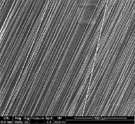
Figure 13.6.
Scanning Electron Micrograph of aligned Polystrene nanofi bers synthesized by
the electrospinning technique. (Unpublished data from the laboratory).
As stated earlier, the electrospun nanofi bers deposited on the grounded
metal collector are in the form of a non-woven mesh. However, fi bers can also be
directed in a particular orientation to enable the synthesis of aligned fi bers (Figure
13.6). ECM molecules in connective tissue like cartilage, ligament, and even skel-
etal muscle have a specifi c orientation, and hence aligned fi bers can provide
contact guidance for cells that can potentially direct their alignment along the
length of the fi bers [88]. This in turn can lead to desirable repair/regeneration of
the tissue. Multiple methods have been reported for the alignment of fi bers syn-
thesized using the electrospinning technique [89-93]. One such method involves
the use of a rotating mandrel in place of a grounded metal plate as the collector.
In this method, when the linear velocity of the rotating mandrel matches that of
the jet, fi bers get deposited on the collecting substrate/ mandrel in a circumferen-
tial manner that generates aligned fi bers (Figure 13.2). This method has been
exploited by Mathews et al. for the alignment of collagen nanofi bers [89] . Another
method that has been reported for nanofi ber alignment makes use of a needle as
the counter electrode that serves to focus the entire set of fi bers from the jet to a
focusing electric fi eld generated due to the sharp pin counter electrode. The
counter electrode is mounted inside a rotating mandrel/drum. Therefore, the
rotating mandrel along with the point counter electrode leads to the alignment of
the nanofi bers [90]. In another report, alignment has been obtained by using a
rotating disc collector instead of a mandrel [91]. The bending instabilities result in
Search WWH ::

Custom Search