Biomedical Engineering Reference
In-Depth Information
0.02
ball wear (mm
3
)
Flat wear (mm
3
)
0.018
0.016
0.014
0.012
0.01
0.008
0.006
0.004
0.002
0
10.00
175.25
240.50
259.50
Residual Compressive Stress (MPa)
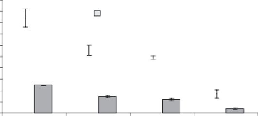
Figure 10.10.
Ball on fl at wear data: alumina ball on alumina fl at showing the clearly
improved wear resistance due to compressive stresses in the surface layer of the fl at. Residual
stresses in fl at measured by XRD.
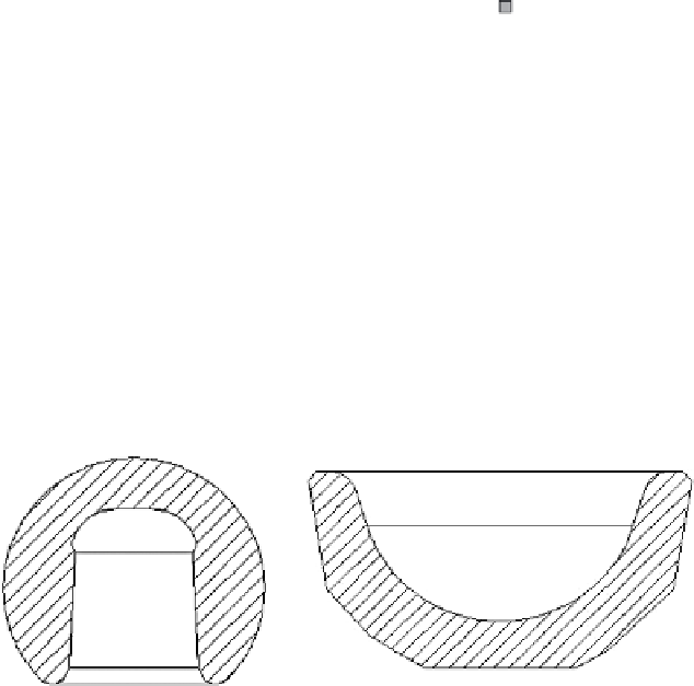
Figure 10.11
Schematic cross-sections of a ball-head with a diameter of 28 mm and a corre-
sponding acetabular cup insert. [Anné, 2005a].
10.6 BALL-HEADS AND CUP INSERTS MADE BY EPD
10.6.1 Introduction
During EPD, the deposit takes the shape imposed by the deposition electrode.
For processing complex shapes, the only shape limitation is the feasibility to
remove the deposit from the electrode after deposition. The deposition electrode
has therefore the shape of the outer surface of the acetabular cup insert and of
the ball-head (Figure 10.11) and consists for the latter of an upper and lower part,
allowing removal of the EPD deposit. Complex geometries like femoral ball-
heads and cup inserts require appropriate design of the counter electrode in order
to generate a constant electric fi eld at the surface of the deposition electrode. The
design of the most suitable counter electrodes needs, therefore, to be supported
by electric fi eld calculations using fi nite element analysis and is discussed in the
next section 10.6.2 .

Search WWH ::

Custom Search