Biomedical Engineering Reference
In-Depth Information
500
1
12
3
4
5
0.8
400
300
0.6
200
0.4
0.2
100
0
0
0
500
1000
1500
2000
2500
Time (s)
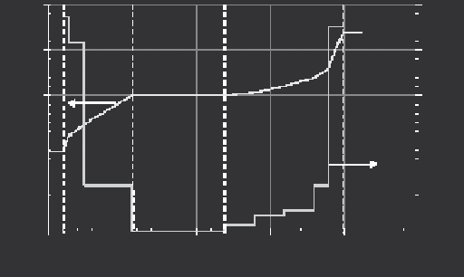
Figure 10.6.
The amount of circulating suspension (ml) and the addition rate (ml/s) of sus-
pension II and III as a function of time during EPD of a graded Al
2
O
3
/ZrO
2
disc. [Anné, 2005a].
for 800 sec. In the last step, the remaining suspension is circulated for 120 sec.
During all the described steps, EPD is continued in the deposition cell. The addi-
tion speed of suspension II and III by pump two is varied in such a way that the
wanted concentration profi le was obtained in both gradient zones. The addition
speed of suspension II and III, which is computer-controlled, and the amount of
circulating suspension as a function of time is given in Figure 10.6.
After EPD, the powder deposits are removed and dried. After at least one
day of drying in air, the green bodies were sintered for one hour at 1550 °C in air.
Sintered cross-sectioned discs are ground, polished and thermally etched for 30
minutes in air at 1350 °C for microstructural analysis. The compositional change is
measured on polished cross-sectioned samples using semi-quantitative electron
probe micro-analysis (JEOL Superprobe 733).
The measured composition profi le on a sintered cross-sectioned FGM plate,
is presented in Figure 10.7, together with the predicted composition profi le
according to the model of section 10.5.2, revealing an excellent correlation
between the experimentally measured and the predicted profi le.
The FGM profi le however is not perfectly symmetrical since only 91 vol. %
Al
2
O
3
is deposited in the fi nal step of EPD. Reaching 100 vol. % Al
2
O
3
is possible
at this end, but the circulating suspensions needs to be changed and this compli-
cates the process. Only limited bending is observed after sintering of the disc.
Based on stress calculations, the FGM profi le given in Figure 10.7, results in
the highest compressive stresses in the outer surface layer of the FGM discs and
the lowest tensile stresses in the core of the disc. The thermally-etched micro-
structures at different locations in the cross-sectioned FGM plate are shown in
Figure 10.8 .
The ZrO
2
(white) and Al
2
O
3
(grey) phases can be clearly differentiated in the
microstructure. The ZrO
2
phase is well dispersed in the Al
2
O
3
matrix in the gradi-
Search WWH ::

Custom Search