Biomedical Engineering Reference
In-Depth Information
(a)
(c)
(b)
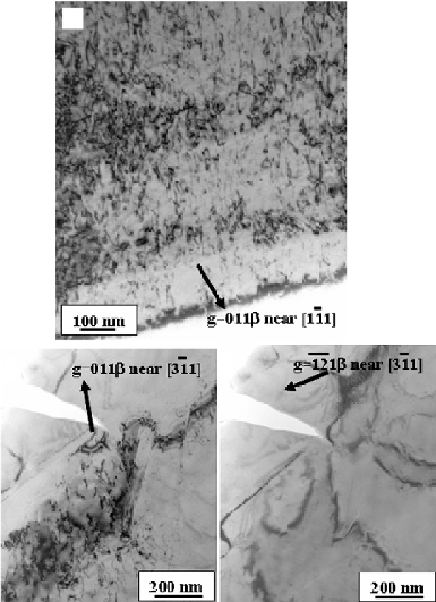
Figure 9.9.
(a) Bright-fi eld two-beam image recorded using
g
= (011)
β
showing diffraction
contrast from the dislocations within the shear bands in the tensile deformed TNZT sample.
A set of bright-fi eld images recorded from the exact same region using different two-beam
imaging conditions are shown in (b) and (c). (b) has been recorded using
g
= (011)
β
while (c)
has been recorded using
g
= (-1-21)
β
. While the dislocation contrast is clearly visible in (b), it is
invisible in (c). [Rajarshi Banerjee et al.
Laser Deposited Ti
-
Nb
-
Zr
-
Ta
Orthopedic Alloys
(J. Bio.
Mater. Res., 78A (2), 2006), 298.]

Search WWH ::

Custom Search