Biomedical Engineering Reference
In-Depth Information
sample.passes.through.the.objective.lens.and.dichromatic.mirror.and.focuses.on.the.detector.pinhole..
Because.the.focal.plane.and.the.detector.pinhole.all.share.the.same.conjugate.plane,.only.the.light.from.
the. focal. plane. can. pass. through. the. detector. pinhole.. his. minimizes. the. background. luorescence.
and.improves.the.contrast.of.the.inal.image..Compared.to.the.light.from.the.focal.plane,.the.efect.of.
the.background.light.on.the.inal.image.is.negligible..he.excitation.ilter.is.used.for.the.selection.of.the.
excitation.wavelength.of.the.light.source,.which.is.especially.important.when.a.multichannel.excitation.
laser.source.is.used..he.dichromatic.mirror.is.used.to.separate.the.excitation.and.emission.light.paths..
he.emission.ilter.selects.the.emission.wavelength.of.the.light.more.narrowly.and.removes.any.traces.of.
excitation.light..To.obtain.a.2D.image,.a.confocal.microscope.is.oten.equipped.with.a.2D.scanner.and.a.
Z.scanning.stage,.which.can.provide.lateral.sections.(
x
-
y
.plane).and.vertical.sections.(
x
-
z
.and.
y
-
z
.planes)..
With.a.fast.resonant.scanner.or.a.spinning.disk,.the.confocal.microscope.can.provide.real-time.imaging.
17.3.1 optical Setup
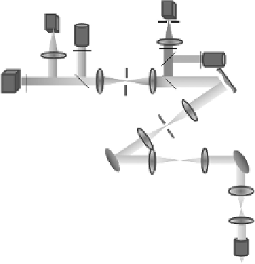
Figure. 17.16. shows. the. layout. of. the. AO. confocal. luorescence. microscope. (AOCFM).. he. whole. sys-
tem.was.designed.and.optimized.using.the.optical.design.sotware.(CODE.V)..A.60×.water-immersion.
objective.with.a.NA.of.1.2.was.used.(Olympus.Microscope,.Center.Valley,.PA).for.imaging.of.both.ixed.
and.living.cells..he.optical.system.includes.three.telescope.relay.subsystems..Lenses.L1.and.L2.image.
the.exit.pupil.of.the.objective.onto.the.Y.scanner..Lenses.L3.and.L4.relay.the.X.scanner.conjugate.onto.
the.Y.scanner..his.design.minimizes.the.movement.of.the.scanning.beam.at.the.exit.pupil.of.the.objec-
tive.and.the.emission.light.at.the.DM,.which.is.important.for.accurate.wavefront.measurement.and.cor-
rection..he.lenses.L2.and.L3.also.serve.as.scanning.lenses..he.current.design.is.optimized.for.an.optical.
scanning.angle.of.4.4°,.which.provides.a.FOV.of.128.μm.on.the.sample.with.the.60×.objective..By.chang-
ing.the.control.signal.to.the.scanners,.the.FOV.can.be.easily.adjusted..Lens.L5.and.L6.image.the.pupil.
of.the.X.scanner.onto.the.DM..Lenses.L7.and.L8.image.the.pupil.of.the.DM.onto.the.wavefront.sensor..
he.DM.(Boston.Micromachines).has.140.actuators.and.3.5.μm.of.stroke..he.diameter.of.the.efective.
aperture.on.the.DM.used.in.this.design.is.4.mm,.which.is.slightly.smaller.than.the.4.4.mm.of.aperture.
of.the.mirror,.to.decrease.edge.efect..he.exit.pupil.of.the.objective.is.7.2.mm..To.match.the.aperture.of.
the.DM.with.the.objective,.the.telescope.formed.by.L1.and.L2.demagniies.the.pupil.from.7.2.to.4.mm.
A.HeNe.laser.emits.light.at.633.nm.for.excitation.of.the.crimson.luorescent.reference.beacon..A.solid-
state.laser.emits.light.at.515.nm.that.excites.yellow.luorescent.protein.(YFP).bred.into.the.sample..F2.
and.F4.are.excitation.ilters..Light.emitted.from.the.reference.beacon.is.passed.through.ilter.F1.to.the.
Helium neon laser
(633 nm)
PMT
Science
camera
Pinhole
L10
L9
Solid-state laser
(515 nm)
DM
F3
F2
L8
F1
DB3
F4
Wavefront
sensor
DB1
DB2
L7
Pinhole
L5
L6
Pinhole
X Scanner
Y Scanner
L4
L3
L2
L1
Tube lens
F: Filter
DB: Dichroic beamsplitters
Objectives
FIGuRE 17.16
System.layout.of.the.adaptive.optics.confocal.microscope.