Biomedical Engineering Reference
In-Depth Information
focal. point,. an. optimization. algorithm. is. enabled. by. varying. the. relative. phase. between. two. seg-
ments.until.the.signal.at.the.focal.point.is.a.maximum.when.the.two.beams.interfere.constructively..
his.can.then.be.repeated.pairwise,.until.all.of.the.remaining.beamlets.interfere.constructively.at.the.
focus..In.a.related.approach,.the.full.pupil.is.illuminated,.rather.than.individual.segments.(Milkie.
2011),.to.avoid.imaging.through.the.small.numerical.aperture.of.a.single.segment..In.this.approach,.
the.wavefront.is.kept.ixed.in.all.but.one.pupil.segment,.which.has.a.phase.ramp.applied.to.it..his.
procedure.is.applied.sequentially.to.each.pupil.segment..Once.the.tilt.has.been.removed.from.each.
of. the. pupil. segments,. the. phase. at. each. segment. is. adjusted. to. obtain. constructive. interference. at.
the.focus.
A.related.approach,.again.using.pupil.segmentation.by.an.LC-SLM,.has.been.used.to.overcome.scat-
tering. in. the. sample. rather. than. refractive. image. aberrations,. as. discussed. earlier.. A. coherent. source.
illuminates.an.LC-SLM.that.segments.the.beam.into.individual.beamlets..A.region.of.interest.or.pattern.
deined.by.a.CCD.camera.is.used.to.detect.constructive.interference.of.the.beamlets..his.is.shown.sche-
matically.in.Figure.8.4..he.phase.of.each.beamlet.is.varied.one.by.one,.or.in.blocks.of.
N
.×.
N
,.and.the.
intensity.in.the.region.of.interest.is.maximized..Once.each.segment.has.been.optimized,.the.beamlets.
interfere.constructively.at.the.region.of.interest.on.the.CCD.camera..In.a.related.approach,.as.shown.
in
.
Figure.8.5
,.
a.luorescent.bead.“guide.star”.is.implanted.in.the.sample.and.the.luorescence.from.the.
guide. star. is. measured. and. optimized. as. the. phase. of. each. segment,. or.
N
.×.
N
. block. of. segments,. is.
varied..When.all.of.the.segments.have.been.optimized,.the.beamlets.from.all.of.the.segments.interfere.
constructively.at.the.guide.star.
In.both.these.techniques—pupil.segmentation.to.overcome.refractive.image.aberrations.and.inter-
ferometric.focusing.to.overcome.scattering—the.high.order.of.the.spatial.light.modulator.is.an.advan-
tage. to. make. high-order. corrections;. however,. the. need. for. optimizing. the. phase. of. each. segment.
makes. this. approach. slow.. Obtaining. an. interferometric. focus. using. an. LC-SLM. can. take. on. the.
order.of.10.minutes..hus,.this.approach.to.AO.will.be.too.slow.for.live.imaging,.which.is.required.for.
biologists.to.dynamically.image.rapidly.changing.samples.such.as.the.mitosis.process.in.
Drosophila
.
embryos.. Most. likely,. LC-SLM. approaches. will. be. limited. in. application. to. imaging. either. ixed.
(frozen).tissues.or.slowly.changing.live.samples,.for.example,.the.slow.variations.that.occur.in.neural.
cell.development.
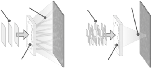
Random
speckle
Focused
light
Shaped
wave
Plane
wave
Strongly
scattering
sample
Strongly
scattering
sample
(a)
(b)
FIGuRE 8.4
(a).A.plane.wave.is.focused.on.a.disordered.medium.and.a.speckle.pattern.is.transmitted..(b).he.
wavefront.of.the.incident.light.is.shaped.so.that.scattering.makes.the.light.focus.at.a.predeined.region.of.interest.on.
a.CCD.camera..(From.Vellekoop,.I..M..and.A..P..Mosk,.
Opt Lett.
,.32,.2309-2311,.2007.)