Biomedical Engineering Reference
In-Depth Information
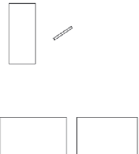
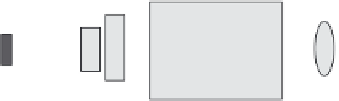
Etalon
Brewster
plate
External
cavity
Output
Isolator
Focusing lens
PM fiber pigtail
TEC
controller
Current source
FIGURE 2.62
The low-noise laser cavity with an etalon and a Brewster plate can be seen. (Courtesy of
Princeton Optronics [PO] and Dr. Chuni Ghosh. With permission.)
2.13 DerivationoftheLinearElectro-Optic(Pockels)Effect
The linear electro-optic effect is the result of distortion of the crystal lattice
caused by an applied electric field. The effect is manifested as an induced
birefringence in the crystal that results in field dependent changes in the
refractive index along various crystal axes, thus affecting the phase of the
transmitted electric field. The electro-optic effect can be derived using
the Index Ellipsoid (IE) notation. A complete derivation for 43 m crystals can
be found in Namba and an example can be found in Yariv [94]. The proce-
dure is to transform the standard IE to a coordinate system rotated to match
the symmetry of the field of interest.
As an example, Figure 2.63 shows an exaggerated diagram of a Double-Y
Mach Zehnder optical logic gate [95] (see also Chapter 3) on a GaAs wafer,
indicating the relative orientation of the device and the crystal. The crystal
axes are indicated using standard notation. It should be noted that due to the
relationship between wafer orientation and the crystal axis of rotation, it is
only practical to apply an external field along a single crystal axis.
The standard IE is written
IE =
1
n
(
x
2
+ + +
y
2
z
2
)
2
r E yz E xz E xy
x
(
+ +
)
(2.7)
41
y
x
2
0
For this discussion, we assume the applied dc field is in the
x
direction only,
along the <100> axis; therefore,


Search WWH ::

Custom Search