Biomedical Engineering Reference
In-Depth Information
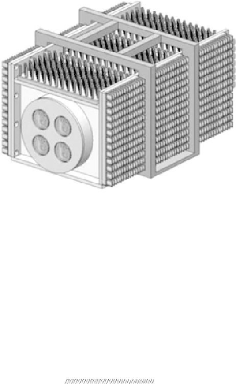
FIGURE 2.60
Diagram of a 40 W output illuminator. The input power for the illuminator is 200 W. The
dimension of the illuminator is 7.5 × 6.5 × 12 in. (Courtesy of Princeton Optronics [PO] and
Dr. Chuni Ghosh. With permission.)
P-contact
P-DBR
Oxide aperture
Active region
N-DBR
Low-doped N-GaAs substrate
N-contact
AR-coating
Light output
FIGURE 2.61
Schematic of the selectively oxidized, bottom-emitting 1064 nm VCSEL structure. (Courtesy of
Princeton Optronics [PO] and Dr. Chuni Ghosh. With permission.)
2.12.12 Low-Noise Laser Cavity
The low-noise laser cavity is shown in Figure 2.62. The optical setup con-
sists of a VCSEL device and an output coupler. A high-quality Etalon and
a Brewster plate in the cavity control the single-wavelength operation and
linear polarization, respectively. The optical isolator prevents optical feed-
back from outside of the cavity to maintain the single-wavelength operation.
The beam is then coupled into a PM fiber with a focusing lens for the mode
matching.


Search WWH ::

Custom Search