Biomedical Engineering Reference
In-Depth Information
Optical
power density
Oscilloscope
display
Oscilloscope
Amplifier
Sample with
cleaved
end faces
GE detector
Detector beam
power monitor
X
Z
HE-NE laser
Y
1.5 µm
Image
converter
tube
1
2
3
Beam splitter
Micropositioner mounts
Rotating mirror
synchronized with
oscilloscope
IC display
X
Y
Side view
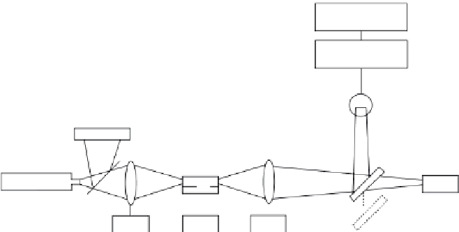
FIGURE 6.1
Mode profile and loss determination setup.
Prism coupling
Z
FIGURE 6.2
Prism coupling waveguide loss measure-
ment technique.
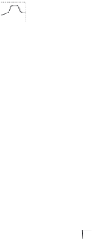
loss information. Figure 6.3 illustrates a typical mode profile obtained using
such an instrument.
Scattering losses can be measured using a fiber-optic probe technique
shown in Figure 6.4. For this technique, micropositioners are accurately con-
trolled to guide a fiber probe along the waveguide (while staying far enough


Search WWH ::

Custom Search