Biomedical Engineering Reference
In-Depth Information
characteristics when making electro-optic modulators or lasers, because
the electric field is a maximum in the optical waveguiding layer. Optimum
coupling of the electrical and optical fields is obtained through the electro-
optic coefficient. Fourth, the heterostructure design naturally leads to the
integration of lasers, waveguides, and modulators without undue etching
of material.
5.7.2 Material Systems: Control of Loss, Refractive
Index, and Electro-Optic Effect
By choosing the AlGaAs system for waveguide fabrication, one is essen-
tially obtaining a wide range of freedom in the choice of band gap for the
material. By varying the percentage of the Al the band gap of the mate-
rial may be changed significantly. The band gap is directly related to the
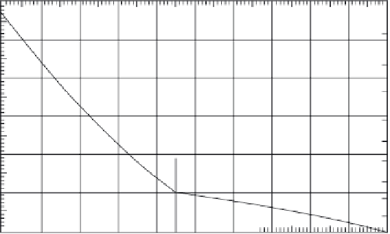
emission and absorption wavelengths of the material. Figure 5.16 shows
the band gap and related wavelength and photon energy of the AlGaAs
system for varying percentages of Al from 0% (GaAs) to 40%. Figure 5.17
shows the index of refractions of AlGaAs versus Al concentration for sev-
eral wavelengths. It is seen that by a proper choice of material composition
in the waveguide core and cladding regions a suitable guiding structure
may be designed.
The strip ridge should be aligned with either the (011) or the (110) crystal-
lographic direction for a modulating electric field perpendicular to the sub-
strate (100) direction. The change in refractive index due to the electro-optic
effect is
0.86
0.84
0.81
0.79
0.76
0.74
0.71
0.69
0.66
0.64
0.61
0.59
0.56
0.00
1.4
1.5
1.6
1.7
1.8
1.8
1.9
2.0
2.1
2.1
2.2
Direct (gamma valley)
Indi
rect (X valley)
0.10
0.20
0.30
0.40
0.50
0.60
0.70
0.80
0.90
1.00
Aluminum concentration
FIGURE 5.16
Minimum energy gap versus aluminum concentration.


Search WWH ::

Custom Search