Biomedical Engineering Reference
In-Depth Information
20
19
18
17
16
15
14
Kuznetsov
13
12
11
10
9
8
Marcatili
7
6
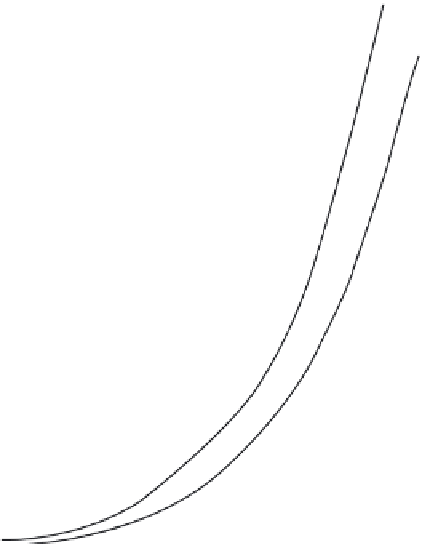
λ
0
= 10.6 µm
a
= 1.5
b
;
b
= 10.0 µm
N
D
= 2 ×10
17
cm
-3
α ~ 1.87 dB cm
-1
5
4
3
Parallel channel
directional coupler
L
versus
C
2
1
0
1
2
3
4
5
6
7
8
9
10
11
12
13
14
(e)
C
(µm)
FIGURE 5.14 (continued)
(e) λ
0
= 10.6 μm;
a
= 1.5
b
;
b
= 10.0 μm;
N
D
= 2 × 10
17
cm
−3
; α ∼ 1.87 db cm
−1
parallel direction channel
directional coupler
L
versus
C
.
Other structures can be formed by growing epitaxial AlGaAs layers on the
substrate. These layers yield a planar waveguide, providing mode confine-
ment in the vertical direction. Some form of etching or ion milling is then
used to define a structure that also provides confinement in the lateral direc-
tion. Three such structures are the raised rib, the buried encapsulated, and
the buried strip-loaded waveguides. Schematic diagrams of these structures
are shown in Figure 5.15.
The first two structures have some obvious disadvantages. The raised rib
design has most of the confined mode present in the rib. This is subject to a
great deal of scattering loss from the etched side walls of the guide. Because
the guide is on the surface, it is also subject to damage and contamination.
The encapsulated design avoids this second pitfall but relies on more com-
plicated lithographic techniques and material growth. This latter aspect

Search WWH ::

Custom Search