Biomedical Engineering Reference
In-Depth Information
8
7
6
N
D
= 2 × 10
17
cm
-3
5
N
D
= 3 × 10
17
cm
-3
4
N
D
= 5 × 10
17
cm
-3
3
N
D
= 8 × 10
17
cm
-3
N
D
= 2 × 10
17
cm
-3
N
D
= 11 × 10
17
cm
-3
2
N
D
= 8 × 10
17
cm
-3
1
N
D
= 5 × 10
17
cm
-3
N
D
= 11 × 10
17
cm
-3
0
1
1.5
2
2.5
3
Aspect ratio
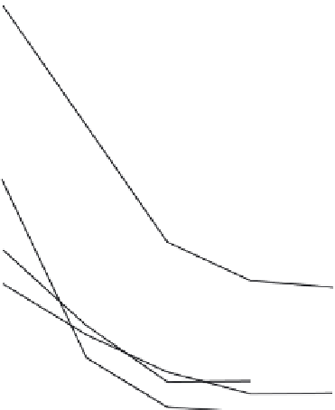
FIGURE 5.10
λ
0
= 1.3 μm—Maximum range of thickness for guiding only the
E E
x
1
⋅
modes.
y
11
through e). Accurate control of the guide separation is very important since
the coupling length
L
decreases exponentially with the ratio
c/e
5
, where
e
5
is
the transverse mode extinction coefficient. In fact, for separations
C
<
e
5
there
will be a significant perturbation upon the optical mode field profile by each
channel upon the other. Predictions of the coupling length for separations
less than
e
5
, therefore, would require a more extensive analysis of the per-
turbation effect.


Search WWH ::

Custom Search