Biomedical Engineering Reference
In-Depth Information
Sensor
×2
DC
DC
PZT
DC-6 kHz
Loop filter
Channel 1
A
(
t
)
Processor
1
B
(
t
)
d
d
t
0.05-100 Hz
BPF
Trigger
Channel 2
output
Det
Processor
2
200-5000 Hz
BPF
0.05-100 Hz
BPF
d
d
t
Signal
output
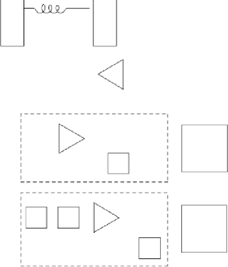
FIGURE 4.14
Signal processing block diagram.
A common fiber sensor signal-processing approach is illustrated in Figure
4.14. The sensor output is split into two bandwidths, one that cover target
dynamics (0.5-100 Hz in channel 1) and one that is sensitive only to high-fre-
quency signals (channel 2). The output of high-frequency bandpass filter is
detected and amplified. The envelope amplitude of the high-frequency sig-
nals behaves like a target with a large steady-state signal; thus, the envelope
of the channel 2 signal is processed in the same way as a channel 1 signal.
Figure 4.15 illustrates the basic output of each channel—a “smoothed” out-
put and its derivative. At time
t
0
in the figure, the target is at its point of clos-
est approach to the sensor, and the processor generates a trigger. The time
t
0
is detected by requiring that the signal derivative
B
(
t
) change while
A
(
t
)
exceeds a threshold
V
th
as shown. If either processor 1 or processor 2 detects
this condition, a trigger is generated. The processors are realized using very
simple analog circuits. One final alternative to this approach is the use of a
carrier generated by a frequency-modulated laser. This detection scheme is
illustrated in Figure 4.16.


Search WWH ::

Custom Search