Biomedical Engineering Reference
In-Depth Information
(a)
(b)
1.00
1.00
0.98
0.95
0.96
y
z
0.90
0.94
y
ϕ
ϕ
x
0.85
0.92
0.80
0.90
0
20
140
Angle between the interface and
E
x
40
60
80
100
120
160
180
0
20
40
60
80
100
120
140
160
180
Angle between the interface and
E
y
θ
x
= ±π/4
θ
x
= ±π/4
(c)
(d)
1.00
1.00
z
xz
xy
yz
0.95
0.95
ϕ
x
0.90
0.90
0.85
0.85
0.80
0.80
0.75
0.75
0.70
0
20
40
60
80
100
120
140
160
180
0
20
40
60
80
100
120
140
160
180
Angle between the interface and
E
x
Interface angle (deg.)
θ
x
= ±π/4
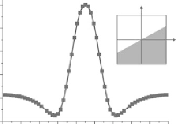
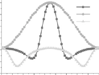
FIgurE 3.7
THG as a function of interface orientation, for an
x
-polarized beam focused by a
NA
=1.2 lens.
(a) THG from an interface parallel to the
z
-axis, as a function of the angle between the interface and the
x
-axis.
Underneath the curve are the far-field harmonic field distributions for various interface angles. (b,c) Similar calcu-
lations for interfaces rotating around the
x
- and
y
-axes. (d) Comparison between the different orientations.
where
k
ω
is the wave vector of the fundamental wave,
k
G
represents the Gouy phase shift, and
k
3ω
is the
wave vector of the harmonic wave.
If we consider scattering with an angle θ relative to the optical axis, and neglect the index mismatch,
we obtain the following phase-matching condition along the
z
axis:
(3.20)
3
(
k
+
k
)
−
cos( )
θ
k
=
0
ω
G
3
ω
implying that coherent scattering will occur at an angle θ such as
3
k
k
cos( )
θ
= +
1
G
(3.21)
3
ω
In the conditions of the simulation (
n
ω
=
n
3ω
= 1.33,
NA
= 1.2), this equation yields θ ≈ 34°, which is
close to the maximum value of the emission pattern.