Biomedical Engineering Reference
In-Depth Information
(a)
(b)
10
12
z
+
θ
peak
10
8
10
4
x
10
0
-
θ
peak
0
20
40
60
80
Angle of emitter with respect to optical axis
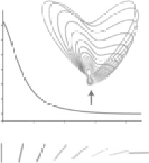
FIgurE 2.14
(a) SHG forward/backward intensity ratio versus the angle between the SHG emitter and the optical
axis. Expected angular distribution of the emitted SHG for different angles between the emitter and the optical axis
(indicated by the arrow). (From Zipfel, W. R. et al. 2003a. Live tissue intrinsic emission microscopy using multiphoton-
excited native fluorescence and second harmonic generation.
Proc. Natl. Acad. Sci. USA
, 100: 7075−7080. Copyright
(2003) National Academy of Sciences, USA.) (b) An excitation beam propagating in the
x
direction and polarized
along the
z
axis is focused onto the specimen. Phase matching between the SHG and the excitation field causes the
SHG radiation to be emitted with two lobes in the forward direction with axes oriented at an angle ±θ
peak
with respect
to the optical axis. (From Moreaux, L., Sandre, O. and Mertz, J. 2000b. Membrane imaging by second-harmonic gen-
eration microscopy.
J. Opt. Soc. Am. B,
17: 1685-1694. With permission of Optical Society of America.)
use an objective with the highest possible NA. Following the same considerations reported in Section
2.2.5, several specifications have to be taken into account when choosing a collection objective lens.
For example, the objective should have optimal transmittance for SHG light without considering the
transmittance in the NIR. However, a higher NA generally corresponds to a shorter working distance.
The working distance of the objective, on the other hand, is a crucial parameter to be considered, since
it limits the maximum thickness of the specimen that can be imaged.
2.3.2.2 Backward Detection
Backward detection is also possible in an SHG microscope, since, in specific conditions, there is a non-
negligible amount of SHG signal emitted in the backward direction. This geometry does not allow
detecting as strong signals as in the forward geometry, because the amount of SHG backward emitted
is generally much lower than the forward emission. However, for some particular samples such as mas-
sive specimens (Guo et al., 1999, Provenzano et al., 2006, Pfeffer et al., 2007, Cicchi et al., 2010) or living
subjects (Konig and Riemann, 2003, Llewellyn et al., 2008), forward detection is intrinsically prevented
and only backward detection is possible. Furthermore, biological tissues are highly scattering media so
that the forward-emitted SHG can be detected in backward geometry by taking advantage of multiple
scattering events. The amount of backscattered signal generated by multiple scattering is extremely low:
in general, it is ranging from 5% to 20% of the forward-emitted signal (Nadiarnykh et al., 2010). In this
condition, the backward geometry is strongly limiting the strength of the detected signal, even if imag-
ing of biological samples is still possible. In the backward modality, the excitation/collection objective
should have optimal transmittance both for NIR and SHG light. If it is not possible to satisfy both condi-
tions, as a general rule, it is preferable to optimize the SHG transmittance.
2.3.2.3 combined Forward
−
Backward Detection
In the same application, a combined forward−backward detection could be required. Such a configura-
tion is based on the detection of both forward and backward scattered light by means of two separated
detectors. The net effect is:
• An increase of the detected signal because the collection cone is not limited to one objective lens
but is extended to two objectives.