Biomedical Engineering Reference
In-Depth Information
2.2 Laser Scanning System
In this section, we are going to describe one of the most important parts of an SHG microscope: the laser
scanning system. Starting from basic principles, we then focus our attention on the different elements
constituting the scanning system (Sheppard et al., 1977, Denk et al., 1990). Then, a brief description of
two particular optical configurations for improving the acquisition speed in an SHG microscope is pro-
vided: a multifocal SHG microscope (Bewersdorf et al., 1998, Buist et al., 1998, Sacconi et al., 2003) and
a digital holographic SHG microscope (Masihzadeh et al., 2010, Shaffer et al., 2010).
2.2.1 Basic Principles of Laser Scanning
In a conventional wide-field microscope, the entire specimen is bathed in light from a light source and
the image can be viewed directly by eye or projected onto an image capture device (CCD). In contrast,
the method of image formation in a laser scanning microscope is fundamentally different. Illumination
is achieved by scanning one (or more) focused beam(s) of laser light across the specimen and by collect-
ing the outcoming light (fluorescence or SHG) point-by-point with a high-sensitivity detector (Sheppard
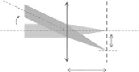
et al., 1977). The basic principles used for performing such scanning are illustrated in Figure 2.3a. As
shown in Figure 2.3, a collimated laser beam propagating parallel to the optical axis is focused by a lens
in a point geometrically defined by the intersection of the optical axis with the focal plane. When the
collimated laser beam is tilted at an angle α with respect to the optical axis, the focal point is located
within the focal plane at a distance
d
from the optical axis. Such distance
d
is related to the tilting angle
α
and to the focal length of the lens
f
by the following equation:
d
=
f
tan α
(2.1)
For small tilting angles, Equation 2.1 can be approximated with the following form (with
α
expressed
in radians):
d
=
f
α
(2.2)
(a)
f
α
d
f
f
1
f
2
Obj
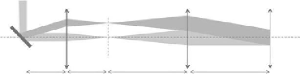
(b)
SS
f
1
f
1
f
2
f
2
FIgurE 2.3
(a) Working principle of a lens with focal length
f
. (b) Schematic path of a beam propagating through
a typical telescopic system composed of two lenses with focal lengths
f
1
and
f
2
, respectively. In the figure SS indicates
the scanning system, while Obj indicates the objective lens.