Biomedical Engineering Reference
In-Depth Information
FIgurE 9.16
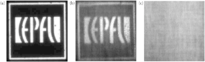
Phase-conjugate scanning images. (a) The wide-field transmission image of the target. The bright
region in this figure indicates the transparent area while the dark region indicates the gold film. (b) The corre-
sponding phase-conjugate scanning image of the target with the target clearly resolved. (c) The scanning image of
the same target without phase conjugation. Since the focus is severely distorted by the turbid medium, the image is
completely blurry. The size of all images is 115 × 115 μm
2
. (Reprinted from Hsieh, C. et al. 2010a. Imaging through
turbid layers by scanning the phase conjugated second harmonic radiation from a nanoparticle,
Optics Express
,
18(20), 20723-20731. With permission of Optical Society of America.)
used for hologram recording by using a phase-only reflective spatial light modulator (SLM), as illus-
trated in Figure 9.15b. When the phase-conjugate illumination is projected in the turbid medium, the
latter converts the pre-distorted wavefront to a clean focal spot at the desired location, as demonstrated
in Hsieh et al
.
(2010c).
However, the holographic SHG characterization of the wavefront distortion introduced by turbid
medium is valid only for a point source emission originating from the position of the BaTiO
3
nanopar-
ticle and scattered through a specific volume of the medium. If the specimen stage holding the physically
interdependent nanoparticle and scattering medium is translated, the phase-conjugate illumination will
propagate through a different volume of the scattering medium and will most likely not produce a clean
focal spot anymore. To form an image, it is therefore essential that the phase-conjugate illumination be
angularly scanned (in opposition to the specimen stage being translated) in order to propagate roughly
through the same volume of the turbid medium, so that the characterization of the wavefront distor-
tion remains valid. Angular scanning of the phase-conjugate illumination leads to a lateral scanning of
the focus on the target plane where the nanoparticle is located, and a pixel-by-pixel image may thus be
formed by using a point detector, for example, a photomultiplier tube (PMT), as in Hsieh et al
.
(2010a).
Figure 9.16b presents such image of a glass slide target bearing a lithographied 130-nm thick gold pattern
logo of École Polytechnique Fédérale de Lausanne (EPFL), obtained through a commercial ground glass
diffuser serving as turbid medium. For comparison, Figure 9.16a shows a bright-field image of the target,
and Figure 9.16c shows the image obtained through the turbid medium, without phase conjugation. The
field of view of the scanning image is dependent on the thickness of the turbid medium and the distance
between the turbid medium and the imaging target, and achievable frame rates are limited by either the
speed of scanning mechanism or the refreshing rate of the SLM.
One of the main interests for such optical phase conjugation is to combine it with, for example, mul-
tiphoton fluorescence microscopy for tissue imaging.
9.7 concluding Remarks
This chapter was intended to help the reader familiarize with holographic SHG imaging. We hope it pro-
vided the required knowledge and references to interpret holographic SHG images, and possibly even to
set up a custom holographic SHG microscope.