Biomedical Engineering Reference
In-Depth Information
(a)
70°
(b)
1.0
40°
25°
ϑ
0.5
0.0
-90
-45
0
45
90
ψ
(deg)
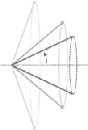
FIgurE 5.3
Dependence of SHG polarization anisotropy on polar angle in cylindrically symmetric sample.
(a) Schematic representation of HRS distributed on the surface of a cone with an aperture angle ϑ. Different angles
are coded in grayscale. (b) SHG polarization anisotropy (SPA) generated by the cylindrical distribution of HRS
emitters in (a) with three different angles: ϑ = 25° (black), ϑ = 40° (dark gray), ϑ = 70° (light gray). The intensity
of SHG is represented as a function of the angle ψ between the laser polarization and the cone axis (see panel a).
The second-order susceptibility tensor, therefore, can be written as
0
0
0
0
0
χ
( )
2
xxy
(5.9)
χ
( )
2
=
χ
( )
2
χ
( )
2
χ
( )
2
0
0
0
yxx
yyy
yzz
0
0
0
χ
( )
2
0
0
zyz
Considering an electric field propagating along the
z
-axis and linearly polarized at an angle ψ with
respect to the
y
-axis (axis of cylindrical symmetry of the sample):
(5.10)
E
= sin
E
ψ
e
+
E
cos
ψ
e
x
y
substituting Equation 5.9 into Equation 5.5, the second-order polarization can be written as
( )
2
)
)
e
y
(5.11)
P
=
2
E
2
sin
ψ
cos
ψ χ
( )
2
e
+
(
E
2
sin
2
ψχ
( )
2
+
E
2
cos
2
ψχ
(
2
yxx x
yxx
yyy
The intensity of SHG (
I
SHG
) is proportional to the square of the second-order polarization:
2
χ
χ
( )
( )
2
2
( )
yyy
I
∝
(
P
)
2
=
E
4
(
χ
( )
2
)
2
sin
2
2
ψ
+
(
sin
2
ψ
+
cos
2
ψ
)
2
(5.12)
SHG
yxx
yxx
The simple case illustrated in Figure 5.2a (extended to
N
molecules) can be described by setting the
polar angle ϑ to zero so that
I
∝
E N
4
2
β
2
cos
4
ψ
(5.13)
SHG
This equation provides a quantitative description of the constructive interference on the basis of SHG
described in the previous section.
In general, Equation 5.12 provides the basis for using SHG measurements to assess the structural
distribution of emitters in a sample. In fact, if
I
SHG
is measured as a function of the laser polarization