Biomedical Engineering Reference
In-Depth Information
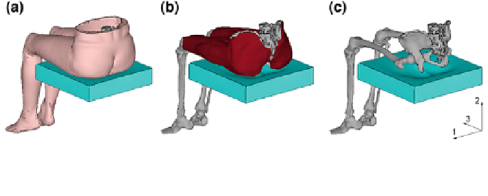
Fig. 7.36 Static simulation of the lower body model BoMo 9 on soft foam cushion at 40 % body
weight loading. a complete model including fat and muscle tissue and foam support, b upper leg
and gluteal muscle groups, c pelvis, femur and tibia structure
ranging from 0 to 300 mm was simulated. A highly resilient foam material similar
to the HR-foam material introduced in
Sects. 4.2.1.2
and
4.2.1.3
was used to
demonstrate the general approach.
7.2.2.1 Body-Support-System (BSS)
The FE-lower body model, Fig.
7.36
, was assigned the following properties (cf.
also
Sect. 5.3.5
, Table
5.13
):
• body mass: 56 kg (via tissue densities and added lumped masses on bone
structure)
• all DOFs of the rigid bone structure constraint, but vertical 2-direction
• tissue material parameters as derived in
Sect. 5.2
• feet unsupported (the feet were modelled as unsupported since it can be
observed from simulation that the femur pitch angle (angle between femur and
horizontal seat surface due to feet ground support) significantly influences the
tissue stress magnitude underneath the ischium)
• revolute joints at hip and knee ankles, and node-to-node modelling of tissue
interfaces
The foam cushion had the dimensions H 9 W 9 D = 400 9 400 9
(0-300) mm, all DOFs of the bottom nodes were fixed. Foam material specifica-
tions were: polyether foam, density: 32 kg/m
3
, CFD (abbr.: compression force
deflection): 3.4 kPa, supplier: B
ASF
, internal identifier: RD-59. The force-
displacement curve obtained from stepwise uniaxial compression testing of foam
RD-59 is given in
Sect. 7.1.1.3
, Fig.
7.3
b. The simulated scenario for the BSS is
exemplarily demonstrated, whereby the lower body model is placed on the soft
foam cushion and gravity loading is applied, Fig.
7.36
.