Biomedical Engineering Reference
In-Depth Information
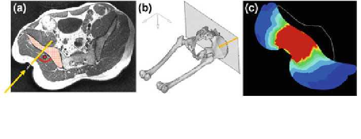
Fig. 5.14 Location of the test point: a indenter axis (arrow) orthogonal to the pelvic bone
surface (hatched), b counter bearing function of pelvic bone (arrow indicates force direction),
c FE model in section cut view
ensure stability during measurement, the ground frame of the apparatus was fixed
to the MRI table.
To additionally measure physiological data such as oxygen saturation, blood
flow, erythrocyte velocity, percentile hemoglobin values (in 2 and 8 mm tissue
depth), an indenter with an incorporated microperfusion-sensor was designed,
Fig.
5.13
c.
Location of the Test Point: The buttock was chosen as the indentation location
since the pelvic bone offers a broadly based support which can be assumed to
capture the indenter loading. In addition the pelvic bone is stiff (undeformable)
compared to the buttock skin/fat and muscle tissue. The pelvic bone provides
defined boundary conditions to guarantee reproducibility in the computational
model. The gluteal region exhibited sufficient skin/fat and muscle tissue to provide
a clearly distinguishable borderline between (deformed) fat and muscle tissue and
bone structure in the MR-images. The test person's hip region was fixed using a
plaster mold fitting tightly into the base frame of the loading apparatus and
embedding the pelvis so that it could not escape the outer loading. To minimize
shear effects on the muscle-bone interface as well as on the fat-muscle interface,
the indenter load direction was set almost orthogonally to the pelvic bone surface,
cf. Fig.
5.14
a. This was verified by MRI pre-recordings. The location of inden-
tation relative to the pelvic bone was primarily chosen with respect to the pelvis
bone acting as a counter bearing to completely carry the compressive indenter
load, cf. Fig.
5.14
b. Thus, the indentation axis was centred relative to the bone
surface, taking into account that the gluteus medius muscle was partially com-
pressed along with the gluteus maximus. The assumption of the pelvic bone being
broad enough to capture the indenter loading can be verified by simulation as
shown in Fig.
5.14
c where the region of highest (von Mises) stress is situated on
the bone surface. The simulated tissue deformation in Fig.
5.14
c is equivalent to
that in the MR-image, Fig.
5.14
a.
Indentation Test with Holding Times: With the objective of separating elastic
from inelastic tissue material properties, a stepwise and cyclic loading and
unloading of the passive gluteal tissue with the subject in a procumbent, relaxed
position was performed, similar to the procedure described in
Sect. 4.2.1.2
.