Biomedical Engineering Reference
In-Depth Information
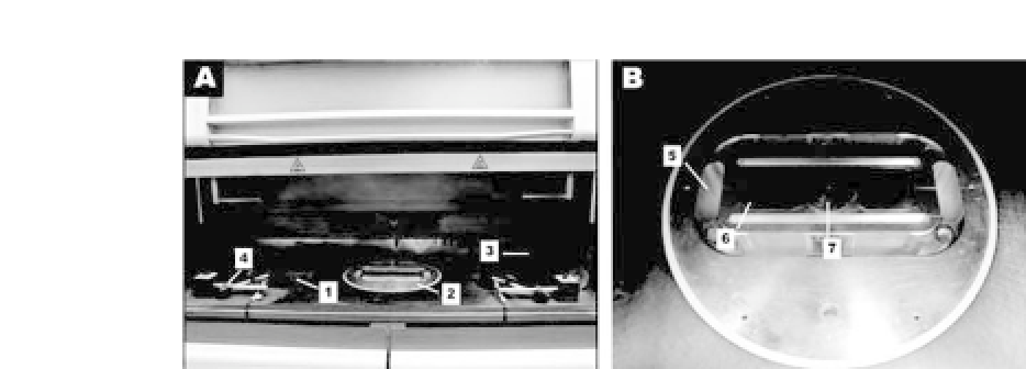
Figure 45.3.
(a) Sinterstation
R
2000 SLS machine; (b) miniature sinter-
ing platform for the modified Sinterstation
R
2000 SLS machine. (1: left
powder tank; 2: build part for original machine and miniature sintering
platform for the modified machine; 3: roller; 4: left sensor; 5: recycle bin;
6: left powder tank for the modified machine; 7: build part for the modified
machine.) See also ColorInsert.
required for a commercial SLS machine in building (sintering) solid
objects. A general view of the sintering section of a commercial
Sinterstation
R
2000 SLS machine (3D Systems, Valencia, CA, USA)
is shown in Fig. 45.3a. A modification of this SLS machine was con-
ducted in order to reduce the consumption of raw materials, that
is, nanocomposite microspheres. As shown in Fig. 45.3b, a minia-
ture sintering platform was designed and installed in the build part
of the Sinterstation
R
2000 SLS machine.
54
The miniature sintering
platformconsistedprimarilyofaminiaturebuildpartandtwopow-
der tanks similar to those of the commercial SLS machine but with
much reduced sizes. The movement of the miniature build part was
synchronized with the existing build part of Sinterstation
R
2000
machine, and the two miniature powder tanks were driven by two
additional stepping motors fixed within the miniature platform. In
the sintering processes, small amounts of microspheres were fed
into the miniature powder tanks with the original powder tanks
being kept empty. Two sensors were installed to sense the roller
positions, and the signals were fed back to a control panel, which
could control the movement of miniature powder tanks. This mod-
ified SLS system only requires small amounts of particulate raw
materials for scaffold fabrication and can sinter good-quality scaf-
folds in an effective and e
cient manner. Similarly, for the same


Search WWH ::

Custom Search