Biomedical Engineering Reference
In-Depth Information
(A)
(B)
(C)
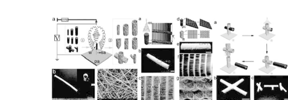
Figure 11.5.
(A): (a) Schematic illustration of fabrication of fibrous tubes
by the electrospinning technique using 3D columnar collectors; b) a fibrous
tube with a diameter of 500
μ
m; c) SEM image of fiber assemblies of the
tubein(b).(B):(a)Schematicillustrationofcollectingprocessusingacylin-
dricalcollectorwithequallyspacedcircularprotrusions(es,electrospinning
process;pc,patternedcollector);(b)afibroustubewithpatternedarchitec-
tures (scale bar
μ
m);
d) schematic illustration of collectors with two different patterns and rele-
vantfibroustube(ft,fibroustube);(e)afibroustubewithtwodifferentpat-
terns (scale bar
=
5 mm); (c) magnified image of (b) (scale bar
=
200
=
5 mm); (f,g) magnified images of two different patterns
μ
of (e) (scale bar
m). (C): (a) Schematic illustration of the process
for fabrication of tubes with multiple interconnected tubular structures;
(b) a crossing tube (scale bar
=
5 mm); (c) tubes with various intercon-
nected tubularstructures (scale bar
=
5 mm).
=
200
cells.Theversatilityofthistechniquegivesroomforfurtherscaffold
improvements.
11.6 Conclusions and Outlook
In this chapter, the technical development of fabricating electro-
spun fibers with different morphologies and configurations (1D,
2D, and 3D) for tissue engineering applications was reviewed. By
modifying electrospinning parameters, fibers with different mor-
phologies, diameters, and structures (core shell, hollow nanofibers,
etc.
) can be fabricated. Nanofibers can be bundled to improve
their mechanical strength. Electrospun mats with different 2D pat-
terned architectures can be fabricated by designing electroconduc-
tive collectors. With well-tailored 3D collectors, fibrous tubes with


Search WWH ::

Custom Search