Biomedical Engineering Reference
In-Depth Information
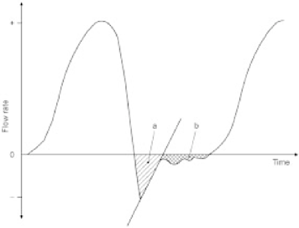
5.10 Example of a single waveform taken from a pulse duplicator apparatus,
required for valve development, as described in ISO 5840:2005 guidelines.
The pulse duplicator records the flow of liquid through the valve during a
simulated heart beat. The hatched area `a' represents the closing volume, or
the volume of fluid required to close the valve. The cross-hatched area in area
`b' represents leakage volume, or the volume of fluid which leaks through the
valve, even after it is closed. Different valve designs will require different
amounts of fluid to close the leaflets, and some designsmay experience residual
leakage, depending upon valve design, leaflet design, and overall construction
techniques. (Figure adapted from ISO 5840:2005 guidelines, `Cardiovascular
implants ± cardiac valve prostheses', available at www.ISO.org.)
and a percutaneous valve prototype during the entire cycle. Note that, despite the
differences in the valve designs and placement techniques, both valves still need
to operate similarly.
5.4.5
Implantation method/ease of use
Implant method and ease of use are additional design considerations which are
very important to the overall success of a procedure. While frequently glossed
over at an engineering level, these considerations are quite important to the
success of the valve, and thus are covered extensively in regulatory testing and
submissions. This would include the use of ancillary devices, such as sizers,
which are used to verify the correct annulus size before the valve is implanted,
as well as valve fixtures and holders, such as used in packaging. In the mitral
position, because the struts of the valve are pointed downward, into the ven-
tricle, it is not possible for the surgeon to directly visualize the struts prior to