Hardware Reference
In-Depth Information
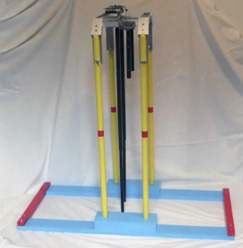
Figure 16-8:
he whole
pendulum
assembly.
he pendulums themselves are attached to M6 threaded rod, which goes through the sides of
the aluminum channel. As shown in Figure 16-9, two lock nuts secure one end; it then passes
through a bearing with a nut securing it, and the pendulum is secured to this with another
nut. Finally the other end of the channel has a nut on one side of the bearing, with a lock nut
on the outside. I drilled out this lock nut's internal nylon washer and glued in the diametri-
cally magnetised magnet. It is vital that this magnet have its face as square as possible to the
rod because this will afect the accuracy of readings that you get.

