Hardware Reference
In-Depth Information
Snap”, the colour snap project shows you how useful half table tennis balls are at acting as a
light difuser. Well, now they are back, and this time they are even more useful. You are going
to mount four tactile button switches on a board, and, in each of the corners, have foam pads
that are slightly taller than the switches. hen, if you put the board switch side down, you can
click each switch in turn by simply pushing the board in that direction. he feel of the switch is
down to the rigidity of the foam pads you use. On the track side of the board, you mount a red/
green LED and cover the board in a half table tennis ball. Let's see how to do that in detail.
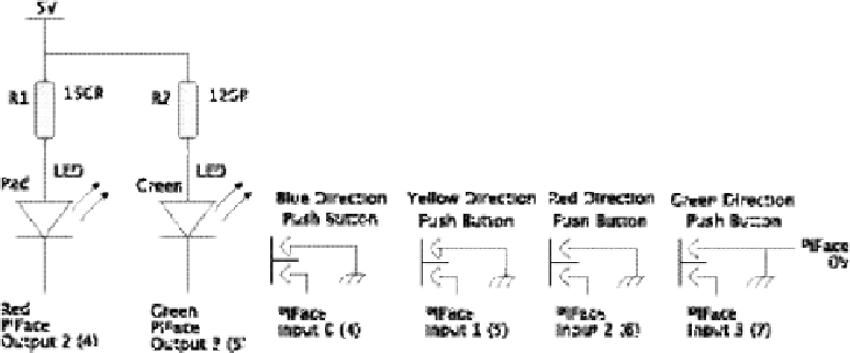
Figure 14-3:
A schematic of
the joystick
button
controller.
The LED needs to be a bright one: Look for one with at least 60 mcd on the red, and 40 mcd
on the green at 20mA - brighter if you can get it; otherwise the switch could look a bit washed
out. I found 90 mcd red and 45 mcd green, which looked good.
Making the Joystick Buttons
Take a small piece of strip board 17 holes long, and 16 strips wide. I like to take the corners of the
board to give it an octagonal shape, just to make it look neater and ensure that the corners don't
snag on the base. Cut the tracks on the back of the board where the dark marks are on Figure
14-4. Make sure that you count the tracks and holes carefully. hen solder a surface mount red/
green LED at the centre of the board, as shown between the two tracks and two track cuts. Make
sure that the orientation mark on the LED is correctly aligned. here are two types of surface
mount LEDs that you can get. One has the LEDs pinned out to the package in parallel; that is, the
two anodes are on one side and the two cathodes on the other. his is sometimes known as a
parallel LED pinout.
he other way is known as
antiparallel,
where one anode and one cathode are
together at each end; these normally have a bar or some other marker, often green, denoting the
cathode. Make sure that you know which you are using. I have designed the board so that the
tracks you need to cut are the same for both versions. However, the links on the component side
are diferent for each LED type. When the LED is in place solder the two surface mount resistors
as shown between the cut marks. If you haven't got surface mount resistors, then one-eighth
watt, or one-tenth watt, resistors should be small enough to mount on the tracks.