Hardware Reference
In-Depth Information
The Output Block
Having a simple system complete means that you don't always have to start coding “at the
beginning” of a system - that is, you don't have to complete the getting-input stage irst.
Instead, you can write the code that controls the door (which is much more fun!).
If you don't have a door lock, you can still follow along by wiring up an LED instead of the lock
to show when the door would be locked.
Connecting the Door Control Circuit
You want the door to stay locked even if the Raspberry Pi crashes, yet in the case of the elec-
tromagnetic lock, a current needs to low to hold the door shut. his functionality is provided
by a changeover relay on the PiFace Digital interface.
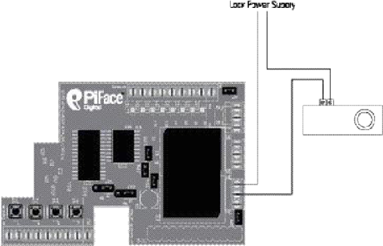
Wire the door lock up as shown in Figure 12-3 or Figure 12-4. You will need an appropriate
power supply for your lock. You can buy plug-in power adapters for a range of voltages.
Check the voltage and current required by your lock. Connect your lock to either the nor-
mally open or normally closed contacts, depending on whether it needs current to unlock the
door, or hold the door locked.
Figure 12-3:
he door lock
circuit diagram
for an
electromagnetic
lock.