Hardware Reference
In-Depth Information
An Interface Board
Although the Raspberry Pi has a general purpose input/output (GPIO) connector that you
can connect to directly, as a beginner, it is easier to use an add-on board. An interface board
can ofer some protection to your Pi against burning out if you get your wires crossed!
PiFace Digital
his chapter uses the PiFace Digital interface because it is very easy to use. PiFace Digital has
eight LEDs on it so that you can start controlling hardware without any electronics knowl-
edge. Later in this chapter you'll connect your own LEDs and switches to PiFace Digital with
the screw terminals. Hopefully you'll go on to use more advanced boards, and eventually you
may want to design an interface board of your own!
In computing,
digital
refers to things that can either be on or off - there's no in between. In contrast,
analogue
devices have many points between their maximum and minimum values. A button is
digital in that it is either on or off. A temperature is an example of something that is analogue.
Setting up PiFace Digital
PiFace Digital communicates using
Serial Peripheral Interface
(SPI) bus. It's a standard means
of connecting peripheral devices to microprocessors. Before you use PiFace Digital with the
Raspberry Pi you need to install some software.
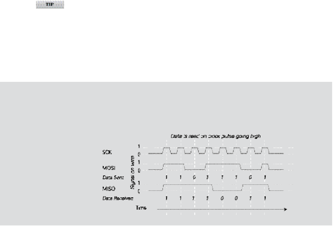
SPI
SPI consists of four wires to communicate data from a master (the microprocessor) to a slave
device (the peripheral). Data is sent
serially
(that is, the voltage on a wire is switched on and
off to communicate a binary number) over time using four wires as shown in Figure 9-1.
Figure 9-1:
Example SPI
transaction: he
microprocessor
sends data
11011101, and
the device sends
11110011.