Biomedical Engineering Reference
In-Depth Information
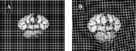
Figure 12.3:
(A) Template and (B) deformed images of a normal mouse brain
cross-section with a representation of a regular finite element mesh superim-
posed upon the image.
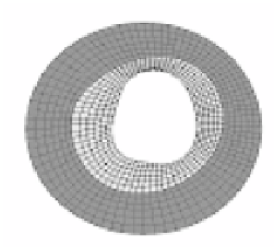
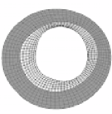
In contrast to regular meshes, irregular meshes are used primarily for phys-
ical deformation applications and conform to physical structures of interest in
the domain of the image data (Fig. 12.4). Irregular meshes also support the defi-
nition of different material models and material properties for specific regions of
the mesh. For example, in Fig. 12.4, the irregular mesh represents a cross-section
B
A
D
C
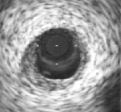
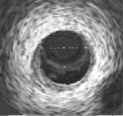
Figure 12.4: A - intravascular ultrasound cross-sectional image of coronary
artery. B - Finite element model of Template image. C - Deformed image of
artery after application of 100 mmHg internal pressure load. D - Deformed finite
element model after Hyperelastic Warping analysis. The grey area of the arterial
wall is represents the intima while the dark gray region represents the adventitia.