Biomedical Engineering Reference
In-Depth Information
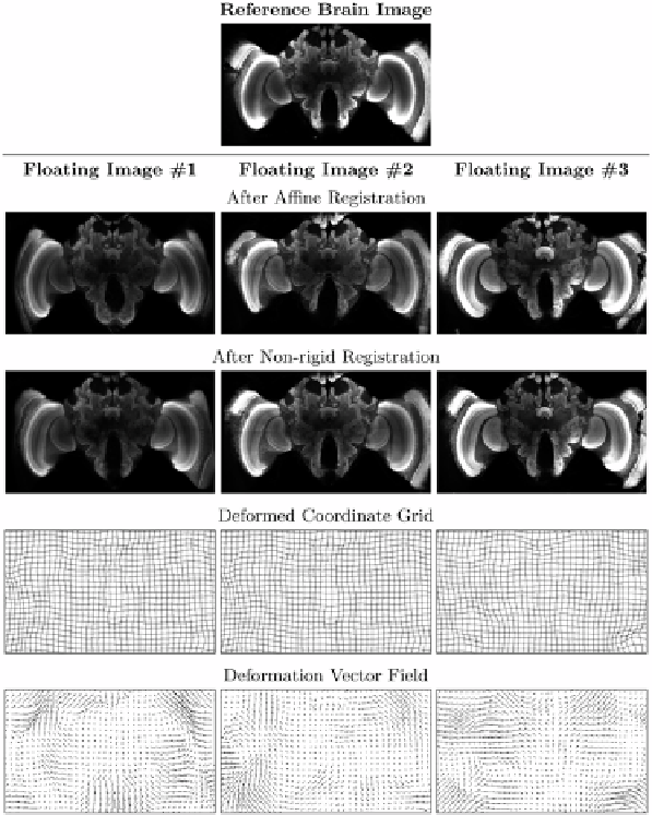
Figure 11.3:
Illustration of inter-subject differences between several individ-
ual bee brains.
Top:
Central axial slice from a 3D microscopy image used as
the reference image for this example.
Second row:
Corresponding slice from
three other bee brains after affine registration.
Third row:
Corresponding slices
after non-rigid registration.
Fourth row:
Deformed coordinate grids.
Fifth row:
deformation vector fields. Note that only the 2D projection of the 3D deformed
coordinate grid and vector field are shown.
same imaging modality to be able to identify corresponding features. Note that
the motion model, i.e., fluid or elastic, does not require single modality images.
However, most algorithms based in which fluid or elastic differential equations
govern the transformation combine these with image similarity terms that are
equivalent to the mean squared difference of image intensities.