Biomedical Engineering Reference
In-Depth Information
a
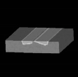
= 100
a
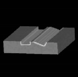
= 3000
Figure 8.12:
Results of the registration with a robust estimator on the regu-
larization term. The reconstructed volumes must be compared to the source
volume. We can handle with local topology changes, while preserving the global
smoothness of the solution.
correction. Figure 8.13 shows the impact of the intensity correction step on the
registration of two volumes. The source image is first corrected using the EM
algorithm, seven classes to model the histogram and a fourth order parametric
correction. Figure 8.13 presents the source image deformed toward the target
image, as well as the difference image. While the registration has failed without
intensity correction due to a very large intensity difference, it has performed
successfully with an intensity correction step. It must be noted that the set of
parameters is the same for both registration processes. That demonstrated the
usefulness of such correction for a non-rigid registration task.
Extensive Results for Two Subjects.
Results of the 3D method are pre-
sented in Figs. 8.14, 8.15, and 8.16. Two 3D MRI-T1 volumes of two different
subjects are registered. The source volume, the target volume and the recon-
structed volume are presented in Fig. 8.14. The reconstructed volume
f
2
(
s
+
ˆ
w
s
)
is computed with the target volume
f
2
and the final displacement field ˆ
w
by the
way of a trilinear interpolation. To assess the quality of the registration, one
must compare the source volume with the reconstructed volume.
We also present the volumes of difference, before and after registration in
Fig. 8.15. In the same figure, the adaptive partition at grid level 3 is also presented
(we do not present further grid levels for readability reasons). The difference
volumes must be interpreted carefully, since we get the superposition of two