Geology Reference
In-Depth Information
d
=
t
/cos
,
(3.1)
δ
where
d
= vertical distance between the surfaces,
t
= true thickness, and
= true dip
(Badgley 1959). The projection can be either up or down from the known point, that
is, from the marker horizon in Fig. 3.20 to either a or b. Be sure to use the same datum
(i.e., sea level) for all measurements. Projections from a surface map need to use the
topographic elevation to find the elevation with respect to sea level. Projections above
the surface of the earth are as valid as projections below the surface; it is not necessary
that the reference surface be confined to the subsurface.
If regional thickness variations are present, the thickness used for projection must
be adjusted according to the location. An isopach map (Chap. 4) provides the informa-
tion necessary to determine the thickness at specific points. In regions of low dip, the
difference between the vertical distance and the true thickness is small. In this situa-
tion an approximate projected surface can be derived by simply adding or subtracting
the thickness between the units to or from the elevation of the marker to obtain the
projected surface (Handley 1954; Jones et al. 1986; Banks 1993).
Projected data can greatly augment the information on a single horizon and can
lead to a significant improvement in the interpreted geometry of the structure. The
increase in data available for contouring may significantly improve the map on the
reference horizon. Inconsistent data on different horizons can be more easily recog-
nized when all data are projected to the same surface. Accurate projection requires
accurate knowledge of the unit thickness and the dip, both of which are likely to con-
tain uncertainties and so a certain amount of “noise” is to be expected in the projected
data set. The interpreted surface and the data will be iteratively improved as the incon-
sistencies are eliminated.
The creation of a composite surface map allows utilization of stratigraphic markers
that are not formation boundaries. The location of any marker horizon separated from
the reference surface by a known stratigraphic interval can be converted to an eleva-
tion on the reference horizon. Even if the marker is not usually mapped, it will provide
important information.
The construction of a projected or composite
-surface includes assumptions that must
be considered in each application. Projection with Eq. 3.1 requires that the dip and
δ
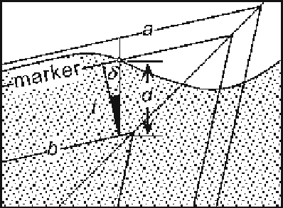
Fig. 3.20.
Vertical cross section showing
the projected distance from a
point (
small circle
) on a marker
horizon to reference surface.
Projections may be done either
upward (to
a
) or downward
(to
b
). The region below
ground level is
patterned
;
d:
vertical distance between
surfaces;
t:
true thickness;
δ
:
true dip