Geology Reference
In-Depth Information
The sign of
E
=-sign
D
if
D
0; = sign
C
if
D
=0 and
C
0; = sign
B
if
C
=
D
=0.
≠
≠
Division by zero is not allowed in Eq. 2.14. The value of
' computed from Eq. 2.7 is
always between the values of 000° and 090° and is equal to 90° if
B
= 0. The true
azimuth,
θ
θ
, of the dip in the complete range from 000° to 360° can be determined from
θ
'
and the signs of cos
α
and cos
β
(Eqs. 2.17 and Table 2.1):
cos
α
=
A
/
E
,
(2.17a)
cos
β
=
B
/
E
,
(2.17b)
where
A
,
B
, and
E
are given by Eqs. 2.16a,b,e above.
As an example, find the analytical solution to the 3-point problem in Fig. 2.20. The
three points have the coordinates, in
xyz
order, of 520 739, 3 754 420, 800; 520 438,
3 753 560, 700; 520 833, 3 753 700, 600. From Eqs. 2.14-2.17, the dip is 22° at an azimuth
of 125°. The leading UTM digits of the
x
and
y
coordinates are identical and need not
be included in the calculation.
2.5
Apparent Dip
Apparent dip,
', is the angle in a plane between the horizontal and some direction
other than the true dip (Fig. 2.19a). To find the apparent dip, let the horizontal angle
between the true and apparent dip be
δ
α
, then
δ
' = arctan (tan
δ
cos
α
) .
(2.18)
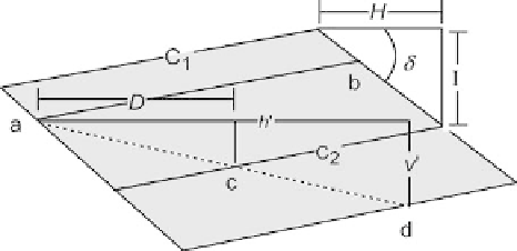
On a completed structure-contour map, the apparent dip in a given direction is found
from
δ
'=arctan(
I
/
h
') ,
(2.19)
where
I
= the contour interval and
h
' = the horizontal distance on the map between
the contours in the direction of interest (Fig. 2.23). If the direction perpendicular to
the contours is selected, then the apparent dip is the true dip. If the strike direction is
selected, the apparent dip is zero.
Fig. 2.23.
Relationships between struc-
ture contours, point elevations,
and dip. Points
a
and
b
are at
the same elevation;
c
and
d
are
at different elevations.
C
1
and
C
2
are structure contours. For
explanation of other symbols,
see text