Geology Reference
In-Depth Information
a log depth of 1 225 ft. The deviation survey gives the coordinates of points above and
below the boundary as 1 200 ft TVD, 50 ft northing, -1 050 ft easting and 1 400 ft TVD,
150 ft northing, -1 150 ft easting. What are the coordinates of the formation boundary?
The subsea depths of the upper and lower points, found by subtracting the log depths
from the elevation of the Kelly bushing are P
1
:
z
= -540 ft and P
2
:
z
= -740 ft, respec-
tively. From Eq. 2.4, the straight-line distance between the two points is
L
= 225 ft.
From Eq. 2.3, the coordinates of a point
r
= 25 ft down the well from the upper point
are -560 ft subsea, 60 ft northing, -1 060 ft easting. Note that negative northing is to
the south and negative easting is to the west.
2.3
Orientations of Lines and Planes
The basic structural measurements at a point are the orientations of lines and planes.
The attitude of a plane is its orientation in three dimensions. The attitude may be given
as the strike and dip (Fig. 2.8). Strike is the orientation of a horizontal line on the plane
and the dip is the angle between the horizontal and the plane, measured perpendicular
to the strike in the downward direction. Compass directions will be given here as the
trend
, which is the azimuth on a 360° compass (Ragan 1985), and will be indicated by
numbers always containing three digits. Strike and dip are written in text form as strike,
dip, dip direction; for example 340, 22NE and represented by the map symbols of
Fig. 2.9a-d. The degree symbol may be written after each angle (i.e., 340°, 22° NE) or
may be omitted for the sake of simplicity, as will be done here (Rowland and Dueben-
dorfer 1994). The alternative form on a quadrant compass is the
bearing
and the dip
(Ragan 1985), for which the same attitude would be written as N20W, 22NE. In subsur-
face geology, where the frame of reference may be a vertical shaft or well bore, the
inclination of a plane may be given as the hade, which is the angle from a downward-
Fig. 2.8.
Attitude of the
shaded
plane
can be given by its strike and
dip, dip vector, or pole
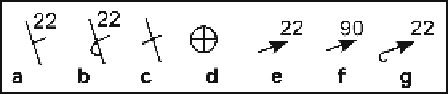
Fig. 2.9.
Map symbols for the attitude of a plane.
a
Strike and dip.
b
Strike and dip of overturned bed.
c
Strike of vertical bed.
d
Horizontal bed.
e
Azimuth and plunge of dip.
f
Facing (stratigraphic up)
direction of vertical bed.
g
Azimuth and plunge of dip, overturned bed