Geology Reference
In-Depth Information
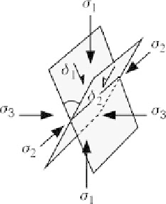
Fig. 12.5.
Geometry of conjugate faults.
δ
i
: Dip vectors of fault planes;
σ
i
: principal stress directions
Equation 12.38 serves as a check on the calculation: it should always equal 1 because
the starting vectors are orthogonal and of unit length. Convert this pole to the bisect-
ing plane (Eqs. 12.37) into the dip vector of the plane as done above. First reverse the
direction of the vector if it points downward (cos
γ
negative) by reversing the signs of
all the direction cosines. Then
cos
α
2
=cos
α
b2
,
(12.39a)
cos
β
2
=cos
β
b2
,
(12.39b)
cos
γ
2
= cos (90 + arccos (cos
γ
b2
)) .
(12.39c)
The azimuth and dip of the planes in Eqs. 12.36 and 12.39 are given by Eqs. 12.4,
12.5 and Table 12.1.
If the two planes being bisected are conjugate faults (Fig. 12.5), then the line of in-
tersection of the faults is the intermediate principal compressive stress axis (
σ
2
), the
line that bisects the acute angle is the maximum principal compressive stress axis (
σ
1
),
and the line that bisects the obtuse angle is the least principal compressive stress
axis (
σ
3
).