Geology Reference
In-Depth Information
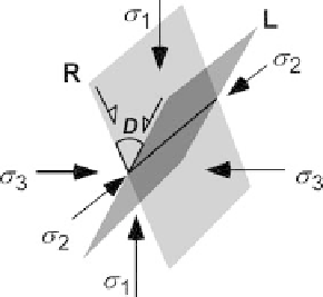
Fig. 1.37.
Conjugate pair of faults re-
lated to orientation of prin-
cipal stresses.
D:
dihedral
angle. The principal stresses
are
σ
3
, in order of
greatest to least compressive
stress.
R
right-lateral fault
plane;
L
left-lateral fault plane;
half-arrows
show the sense of
shear on each plane
σ
1
,
σ
2
, and
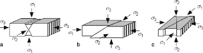
Fig. 1.38.
Fault orientations at the surface of the earth predicted from Andersonian stress theory.
a
Normal.
b
Reverse.
c
Strike slip
and the intermediate principal stress,
σ
2
, is parallel to the line of intersection of the
two faults. The slip directions are directly related to the orientation of the principal
stresses (Fig. 1.37), with one set being right lateral (dextral) and the other set left
lateral (sinestral).
The surface of the ground is a plane of zero shear stress and therefore one of the
principal stresses is perpendicular to the surface and the other two principal stresses
lie in the plane of the surface (Anderson 1905, 1951). From the experimental relation-
ship between fault geometry and stress (Fig. 1.37), this leads to a prediction of the
three most common fault types and their dips (Fig. 1.38). Relative to the horizontal,
normal faults typically dip 60°, reverse faults average 30°, and strike-slip faults are
vertical.
The predicted dips in Fig. 1.38 are good for a first approximation, but there are
many exceptions. Fault orientations may be controlled by lithologic differences,
changes in the orientations of the stress field below the surface of the ground, and by
the presence of pre-existing zones of weakness. True triaxial stress states can result
in the formation of two pairs of conjugate faults having the same dips but slightly
different strikes, forming a rhombohedral pattern of fault blocks (Oertel 1965). Oertel
faults are likely to be arranged in low-angle conjugate pairs that are 10-30° oblique to
each other. Faults will rotate to different dips as the enclosing beds rotate. Even with
all the exceptions, it is still common for faults to have the approximate orientations
given in Fig. 1.38.