Geology Reference
In-Depth Information
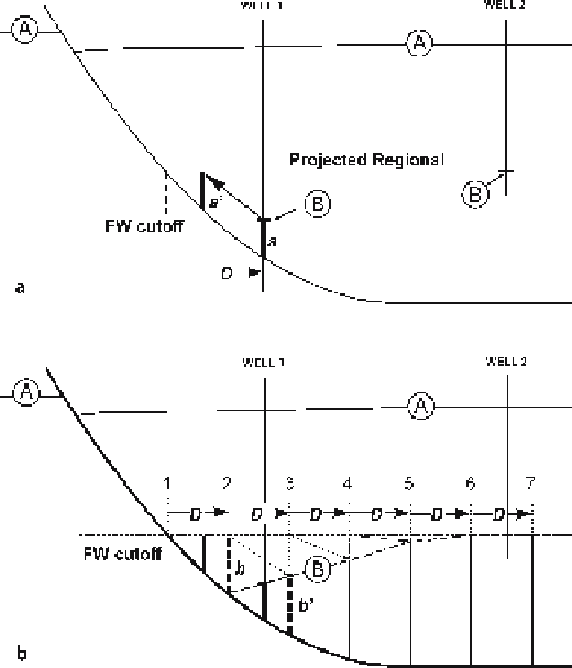
Fig. 11.49.
Determination of rollover
shape from fault shape using
vertical simple shear (modi-
fied from Verrall 1982).
Marker A has been used to
find the fault shape by the
method of Fig. 11.48. The
regional for bed B is obtained
from well 2.
a
Determination
of heave,
D
.
b
Construction of
position of marker horizon B;
predicted shape is
dashed
Once the shape of the fault is known, the geometry of any bed in the rollover can be
determined if its regional position and the location of at least one point in the rollover
is known (for example, B in Fig. 11.49a). The steps are as follows:
1. Find the regional by projecting a straight line along the regional from a known
position of the regional in the hangingwall (B in well 2) to where it intersects the
fault at the footwall cutoff. If the regional is known from the footwall, that level can
be used for projection (Fig. 11.49a).
2. Drop a perpendicular from the regional, through point B in the rollover (in well 1)
to the fault. The length
a
is the depth to the fault (Fig. 11.49a).
3. Move length
a
up the fault until it just touches the regional at
a
'
(Fig. 11.49a).
4. The distance along the regional between
a
and
a
'
, is the heave (
D
) of marker B on
the fault (Fig. 11.49a).
5. Starting from the footwall cutoff, mark equal distances along the regional at a spac-
ing equal to
D
and draw perpendiculars to form the working lines 2-7 (Fig. 11.49b).
6. Measure the distance between the regional and the fault along working line 2 (
b
)
and shift it one heave increment down the fault in the direction of displacement to
line 3 (
b
'
) where the top of the measured line marks the position of marker B
(Fig. 11.49b).