Geology Reference
In-Depth Information
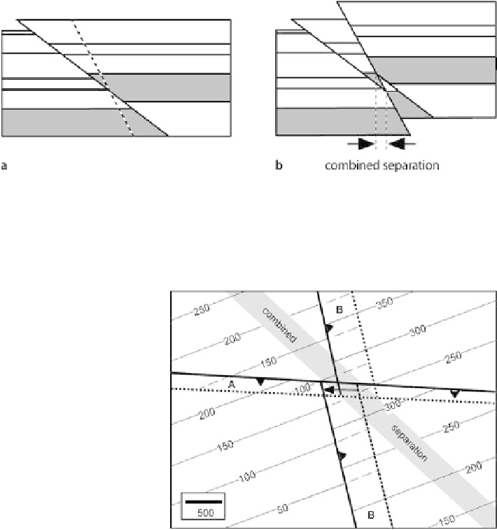
Fig. 8.44.
Evolution of crossing reverse faults having the same dip direction. The cross sections ap-
proximate the evolution along an east-west cross section through the center of Fig. 8.43c.
a
First fault
displacement showing the
dashed
trace of the second fault.
b
Displacement on the second fault.
Dotted
lines
bound the zone of combined stratigraphic separation for the
shaded
horizon
Fig. 8.45.
Structure contour map of cross-
ing reverse faults. Fault
A
is
older, strikes 273°, and has a
heave of 100 units, up on the
south; fault
B
has a heave of
200 units, strikes 347° and is up
on the east with displacement
parallel to the trace of fault
A
(
arrow
).
Thin solid lines
are
contours on the marker hori-
zon. The intersection lines of
faults with the contoured hori-
zon are
wide lines
.
Dashed con-
tours
are hidden below faults.
(After Dickinson 1954)
Just as for normal faults, a variety of different geometries are produced by the in-
tersection of reverse faults of varying attitudes, amounts and directions of slip, and
that cut marker horizons of differing attitudes. The map of Fig. 8.45 is the result of
displacement of a southeast dipping bed by two orthogonal reverse faults, fault A being
the older. Figure 8.46 shows the evolution of two parallel thrusts having opposite dips.
The evolution of an east-west cross section of a structure approximately like that of
Fig. 8.46c is shown in Fig. 8.47. A vertical well in the zone of combined separation would
have three fault cuts and penetrate the top of the shaded unit twice. Even though the
two faults thicken the section, a unit within the zone of combined separation can be
reduced in thickness by the second fault. In the region labeled “T” (Fig. 8.47b) the shaded
unit is thinned by the crosscutting reverse faults and the middle fault cut could be
mistaken for a normal fault downthrown to the west.