Geology Reference
In-Depth Information
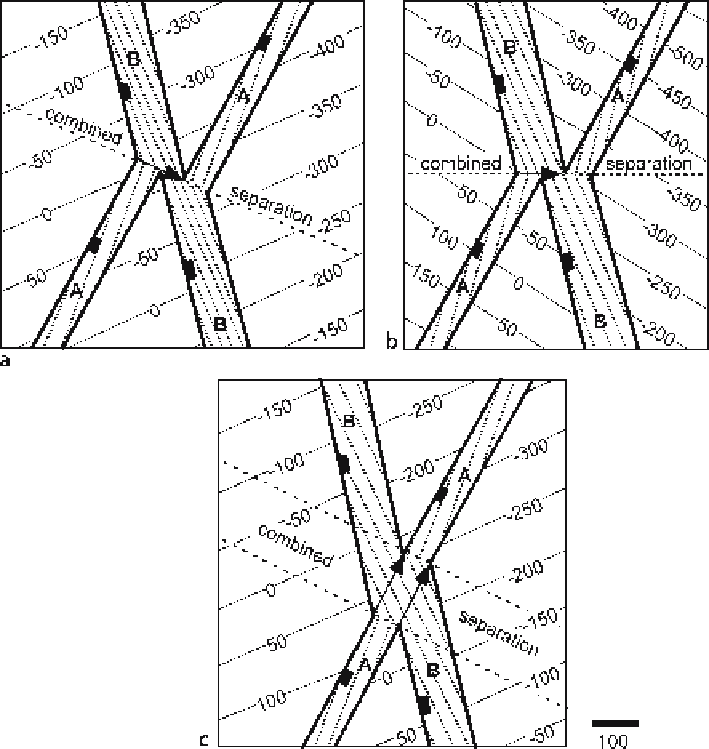
Fig. 8.42.
Structure contour maps showing effect of the slip direction of the later fault (
B
) on the inter-
section geometry between normal-separation faults.
Thin solid contours
are on the marker horizon,
dotted contours
are on the faults. Fault
A
strikes 020°, is older, and has a throw of 100 units. Fault
B
strikes 335° and has a throw of 200 units. The slip is downthrown in the direction of the
arrows
. Note
that the strikes of the faults, as shown by the structure contours, are not the same as the trend of the
fault cutoff lines.
a
The slip direction of fault
B
is obliquely down to the southeast, in the dip direction
of
A
. The attitude of the marker horizon is the same as in Fig. 8.41.
b
The slip direction of fault
B
is
obliquely down to the east.
c
The slip direction of fault
B
is obliquely down to the northeast, in the
strike direction of
A
. The attitude of the marker horizon is the same as in Fig. 8.41
A cross section (Fig. 8.44) shows the evolution of two reverse faults having the same
dip direction, like those in the previous map (Fig. 8.43c). In the zone of combined strati-
graphic separation between the dashed lines, a vertical well would cut three faults, but
the top of the shaded unit would be penetrated only twice. Inside this zone the throw
on the top of the shaded unit is the combined value for both thrusts.